140 Appendix A – Interface Pin Assignments TB9100/P25 CG/P25 TAG Installation and Operation Manual
© Tait Limited March 2014
DC Input to 12V PA
The pin allocations for the 2-way DC input connector are shown below.
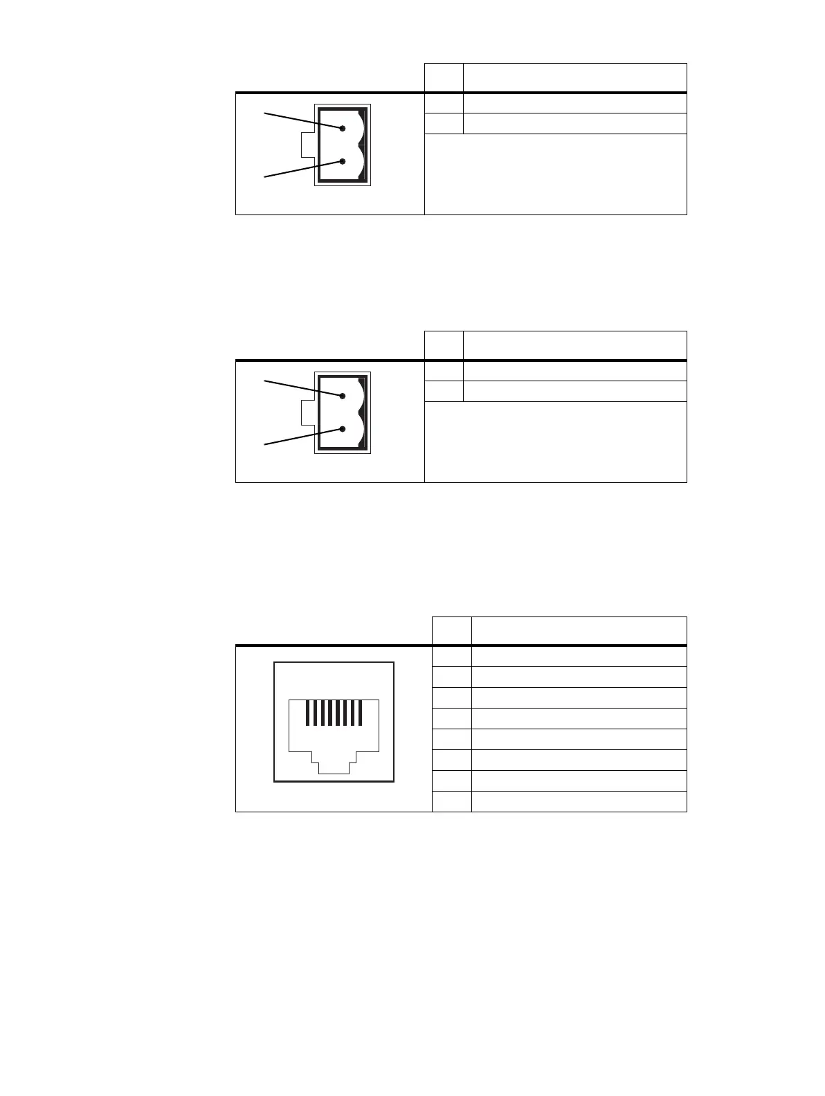
Microphone Connection
The pin allocations for the microphone socket are given in the following
table.
Pin Description
1 +V output
2 ground
2-pin connector - rear view
b
c
Pin Description
1 +V output
2 ground
2-pin connector - rear view
b
c
Pin Description
1 not connected
2 not connected
3 not connected
4 PTT
5 voice band (microphone) input
6 microphone ground
7 not connected
8 not connected
12345678
front view

 Loading...


