14 Description TB9100/P25 CG/P25 TAG Installation and Operation Manual
© Tait Limited March 2014
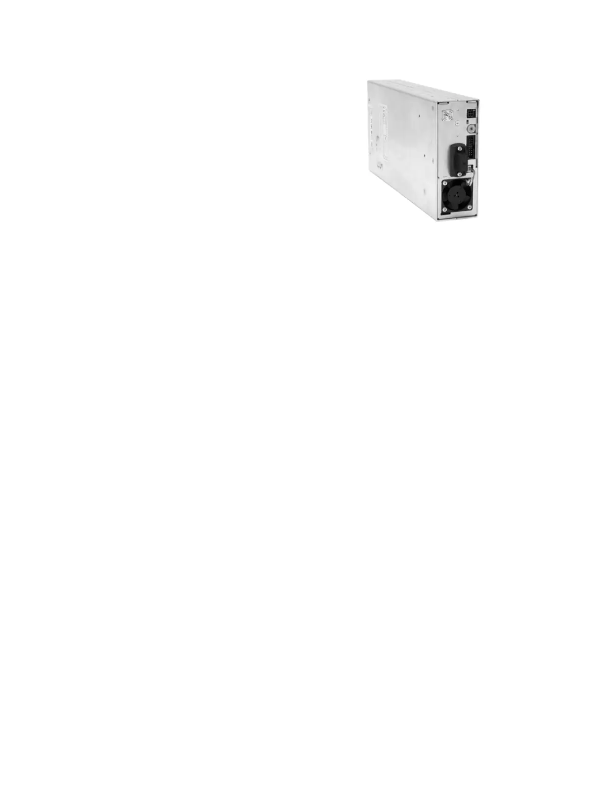
Base Station Reciter
The reciter module comprises the
receiver, exciter and digital control
circuitry. It also incorporates the
network board, which provides the
Ethernet interface, the analog line
interface, and general purpose digital
inputs and outputs.
Reciters are installed in the subrack
from right to left (viewed from the
front), with the right-hand position
corresponding to position 1 on the
control panel. Only the reciter in
position 1 can communicate with the PMU (if fitted).
It is not possible to convert a reciter to a gateway module.
Gateway Modules
The gateway module of the console gateway and trunked analog gateway
appears identical to the reciter of the base station. However, they are
electronically distinct. The console gateway and trunked analog gateway
have no RF capability. They perform P25 encryption and decryption at the
analog line, which the base station is incapable of.
Gateway modules are installed in the subrack from right to left (viewed from
the front), with the right-hand position corresponding to position 1 on the
control panel. Only the gateway module in position 1 can communicate
with the PMU (if fitted).
It is not possible to convert a gateway module into a reciter.

 Loading...


