TB9100/P25 CG/P25 TAG Installation and Operation Manual Appendix B – Inter-Module Connections 147
© Tait Limited March 2014
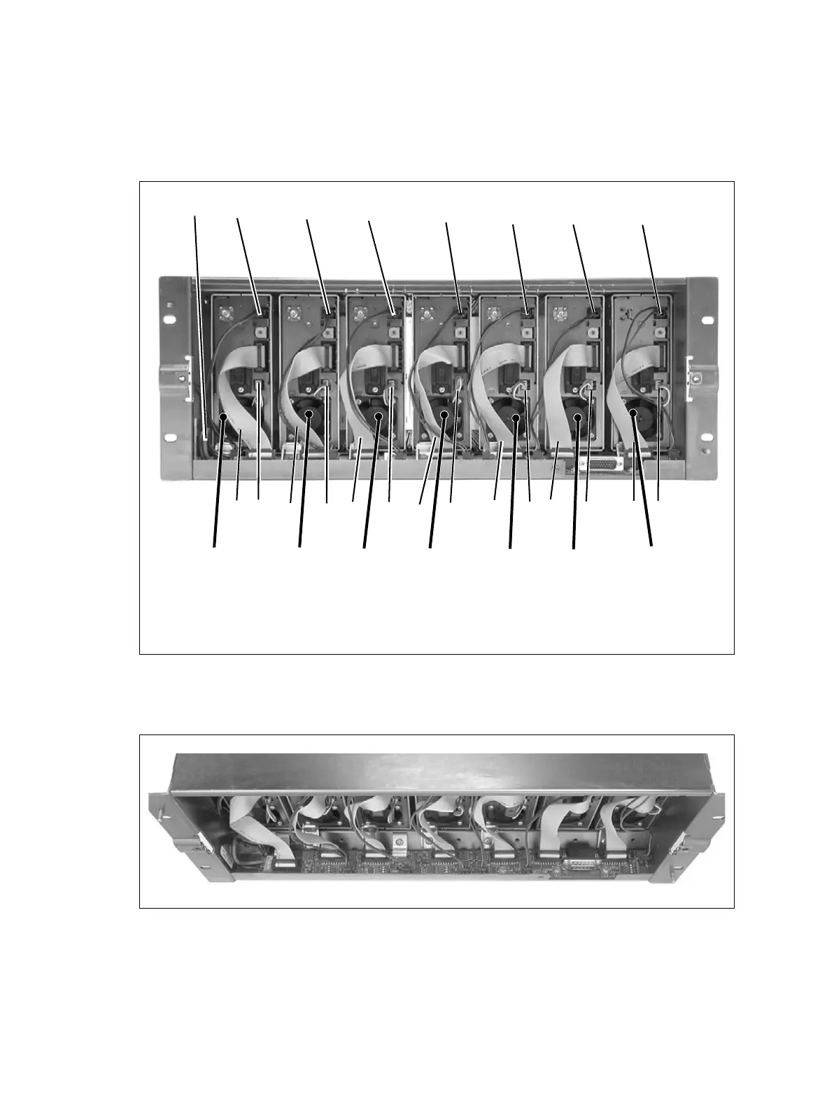
Seven Reciters
The connections between modules at the front of a base station with seven
reciters are shown below.
The following diagram shows the subrack interconnect board connections
for this configuration.
Internal connections for seven reciters
b
28VDC high current input from DC input terminal
block
d
DC output for reciter fan
c
28VDC low current input from subrack
interconnect board
e
system control bus
b
c
e
d
c
c
reciter 4
reciter 2
e
d
e
reciter 3
reciter 5
d
d
e
e
e
c
reciter 1
d
reciter 6
reciter 7
e
d
c
c
c
d

 Loading...


