TB9100/P25 CG/P25 TAG Installation and Operation Manual Technical Description 119
© Tait Limited March 2014
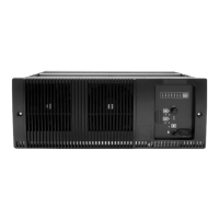
The PMU occupies its normal slot at the left end of the subrack, with the
PA directly beside it. The reciter occupies the slot at the right of the subrack.
Unlike the 5W and 50W PAs, the 100W PA is mounted horizontally with
the heatsink facing upwards. It is also fitted with an airflow duct to channel
the airflow from the cooling fan through the heatsink fins.
8.2 Reciter Module Operation
The reciter consists of an RF, a digital and a network board. Figure 8.3 on
page 122 shows the configuration of the main circuit blocks, and the main
inputs and outputs of the reciter.
Receiver RF -
VHF Reciter
The incoming RF signal is fed through a low pass filter, then through a band
pass “doublet” filter, and finally through a high pass filter. The signal is then
amplified and passed through another band pass “doublet” filter before being
passed to the mixer, where it is converted down to the 16.9MHz IF
(intermediate frequency). A VCO (voltage controlled oscillator) provides a
+17dBm input to the mixer, and a diplexer terminates the mixer IF port in
50Ω.. The signal from the mixer is fed through a 2-pole crystal filter to the
IF amplifier which provides enough gain to drive the digital receiver. Note
that there are two 2-pole crystal filters, one for narrow bandwidth and one
for wide bandwidth. The appropriate filter is selected by software-controlled
PIN switches, according to the bandwidth selected in the CSS. The signal
is finally passed to the ADC (analog-to-digital converter) in the digital
receiver via an anti-alias filter.
Receiver RF -
UHF Reciter
The incoming RF signal is fed through a band-pass filter, followed by a
simple low-pass network. It then passes through further stages of filtering,
amplification and AGC
1
(automatic gain control) before being fed to the
mixer where it is converted down to the 70.1MHz IF (intermediate
frequency). A VCO (voltage controlled oscillator) provides a +17dBm
input to the mixer, and a diplexer terminates the mixer IF port in 50Ω.. The
signal from the mixer is fed through a 4-pole crystal filter to the IF amplifier
which provides enough gain to drive the digital receiver. The signal is finally
passed to the ADC (analog-to-digital converter) in the digital receiver via an
anti-alias filter.
Exciter Circuitry P25 digital or analog FM audio signals from the network, analog line or
microphone are fed to the exciter RF circuitry via the digital board DSP
(digital signal processor) and CODECs (encoder/decoder). These
modulating signals are applied to the exciter at two points (dual point
modulation): low frequency modulation is via the FCL (frequency control
loop), which modulates the exciter synthesizer’s frequency reference, and
speech band modulation is supplied directly to the VCO.
1. AGC is available in H-band reciters only. It can be disabled using the CSS.

 Loading...