TB9100/P25 CG/P25 TAG Installation and Operation Manual Operation 87
© Tait Limited March 2014
PMU
The only controls on the PMU are the on/off switches on the rear panel for
the AC and DC modules, and the indicator LEDs visible through a slot in
the front panel.
Warning The AC and DC module on/off switches do not
totally isolate the internal circuitry of the PMU from the AC or
DC power supplies. You must disconnect the AC and DC sup-
plies from the PMU before dismantling or carrying out any
maintenance. Refer to the service manual for the correct servic-
ing procedures.
AC Module On/Off
Switch
This switch turns the AC input to the PMU on and off. Note that this
switch breaks only the phase circuit, not the neutral.
On switches fitted to PMUs up to November 2008, the red button is
“in” when on, and “out” when off. On switches fitted from November
2008 onwards, the red button remains “out” whether on or off.
DC Module On/Off
Switch
This switch turns the DC output from the PMU on and off. Note that this
switch does not disconnect power from the DC converter itself. It disables
the converter by switching off its control circuitry. Even when the DC
converter is off, the DC input is still connected to its power circuitry.
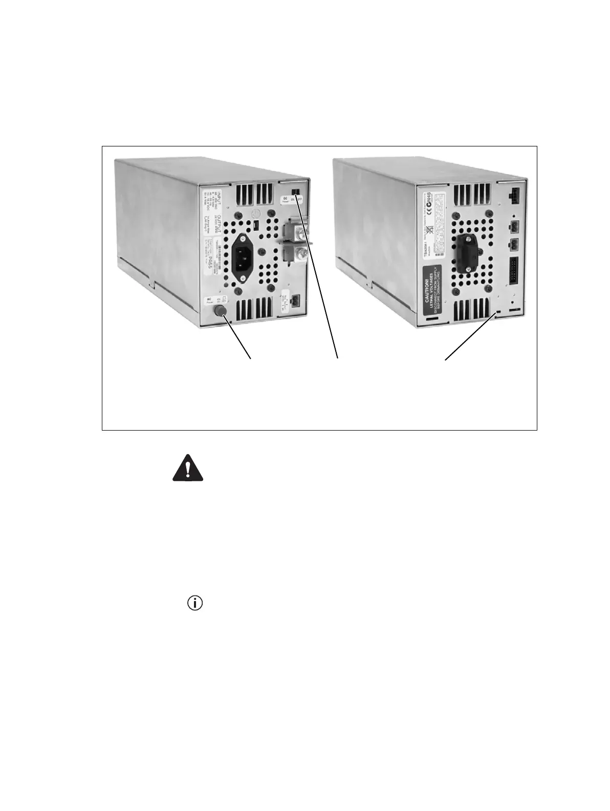
Figure 4.5 Operating controls on the PMU
b
AC module on/off switch
d
indicator LEDs
c
DC module on/off switch
bc
rear view
d
front view

 Loading...


