84 Operation TB9100/P25 CG/P25 TAG Installation and Operation Manual
© Tait Limited March 2014
4.4 Module LED Indicators and Switches
Additional status information is displayed by LEDs in individual modules.
The PMU has switches that let you turn the AC and DC modules off.
Reciter
The reciter indicator LEDs are located on the front and on the rear.
Front View The indicator LEDs on the front are visible through a slot in the front panel.
These LEDs provide the following information about the state of the reciter:
■ steady green - the reciter is powered up
■ flashing red - one or more alarms have been generated; you can use the
CSS to find out more details about the alarms.
The alarm LED will flash whenever an alarm is generated, whether or
not this alarm has been disabled in the CSS.
The rotary hex switch mounted on the front panel is not used and has no
effect on the operation of the reciter.
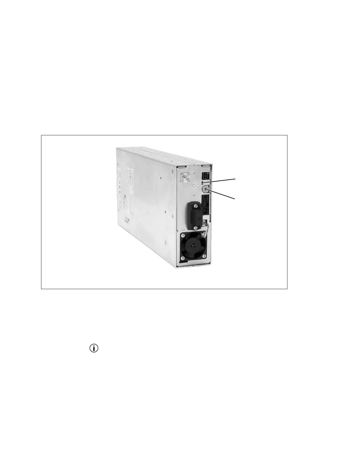
Figure 4.2 Indicator LEDs on the front of the reciter
b
indicator LEDs
c
hex switch
c
b

 Loading...


