TB9100/P25 CG/P25 TAG Installation and Operation Manual Appendix B – Inter-Module Connections 141
© Tait Limited March 2014
Appendix B – Inter-Module Connections
Notice In the following sample photographs, note that the system
control bus cables for the reciters are carefully bent around the reciter
fans, to ensure an adequate air supply.
5 or 50W Base Station
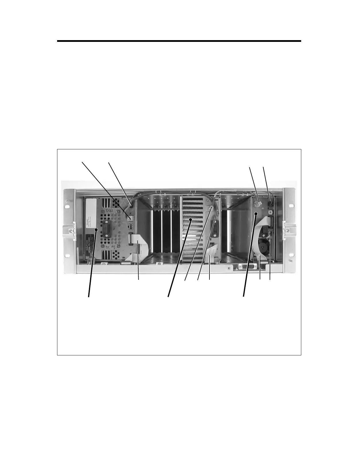
The connections between modules at the front of a 5 or 50W base station
are shown below.
5 or 50W base station internal connections
b
28VDC high current output for PA
f
DC output for reciter fan
c
28VDC low current output for reciter (obscured)
g
system control bus
d
RF output to PA
h
28VDC high current input cable from PMU
e
28VDC low current input from PMU
i
RF input from reciter
bc
g
h
d
i
e
f
PA
PMU
reciter
g
g

 Loading...


