132 Technical Description TB9100/P25 CG/P25 TAG Installation and Operation Manual
© Tait Limited March 2014
8.5 Control Panel
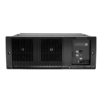
The control panel is designed to be the link between the user and the
modules in the subrack. The circuitry for the operation of the control panel
is located on a board mounted behind its front face. All communication
between the modules and the control panel is via the system control bus.
The control panel allows you to select which reciter is connected to the
control panel. This reciter will then drive the status LEDs, and respond to
inputs from the controls on the control panel.
When a reciter is not fitted and that subrack position is selected, the status
LEDs will reflect the status of the channel which was selected before the
change was made. This is because there is no reciter present in the newly
selected position to update or clear the status of the LEDs.
Only the power and alarm LEDs are used in a gateway.
The channel LEDs use different colors to indicate the currently selected
reciter. They also provide real-time status information for any reciter
installed in the subrack. Any reciter can update (in real time) the channel
LEDs to display one of two possible reciter status signals:
■ Rx gate
■ alarm
Links on the multi-reciter subrack interconnect board allow you to choose
which status signal (either Rx gate or alarm) is connected to the channel
LEDs. Links on the control panel board also allow you to select which color
(either red or green) will be used for the selected status signal. The other
color will then be used to indicate the currently selected reciter. The default
colors are:
■ green for Rx gate
■ red for alarm
If the LED for the currently selected reciter receives a status signal, it will
change to orange. Refer to “Configuring the Control Panel Board” on
page 99 and “Configuring the Subrack Interconnect Board” on page 112
for more information.
Control Circuitry The control panel board translates:
■ I
2
C messages from the reciter into an appropriate response on the LEDs
■ control panel button inputs (except the channel button) and fan rotation
inputs from both fans into appropriate I
2
C messages.

 Loading...