Behavior. Bandwidth refers to the range of frequencies the instrument can acquire and display accurately with less than 3 dB
attenuation. Each input channel has its own bandwidth selection.
To take accurate measurements, the input frequency should be much less than the rated bandwidth of the instrument. A good
rule to follow is to ensure the bandwidth of the instrument system is three to five times the bandwidth of the signal that you want
to measure.
What do you want to do next?
Continue to learn about the Vertical Setup controls.
Return to the Vertical Setup control window overview.
Bus pattern condition
For the supported instruments, use the control to select how many occurrences of the pattern to detect before the instrument
triggers.
Bus selection
For the supported instruments, use the control to select the Bus on which to trigger from the list of bus setups.
Bus time condition
For the supported instruments, click the Time entry box and enter a value with the keypad or use the multipurpose knobs to
select a value.
Trigger logic state condition
For various trigger types, in the Trigger if Logic State drop-down list, select True to trigger the instrument when the logic patterns
are true. Select False to trigger the instrument when the logic patterns are false.
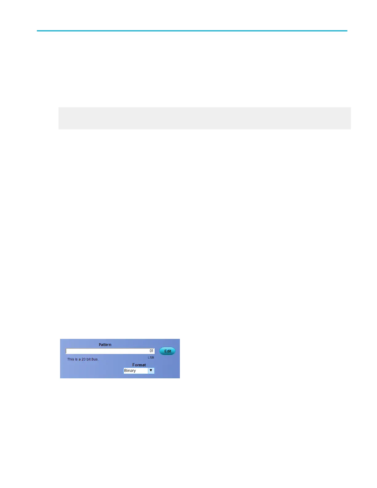
Set the parallel bus pattern
For the supported instruments, use the controls to set up the Parallel Bus parameters. Click the Edit button to access the Pattern
Editor dialog box.
For information on the Pattern Editor dialog box, click the buttons.
■
Bus Pattern
■
Digital Pattern
Oscilloscope reference
DPO70000SX, MSO/DPO70000DX, MSO/DPO70000C, DPO7000C, and MSO/DPO5000B Series 845
 Loading...
