
Do you have a question about the Tektronix TDS 200-Series and is the answer not in the manual?
| Channels | 2 or 4 |
|---|---|
| Record Length | 2.5k points |
| Input Coupling | AC, DC, GND |
| Sample Rate | 1 GS/s |
| Display | 5.7-inch monochrome LCD |
| Vertical Resolution | 8-bit |
| Trigger Modes | Edge, Video, Pulse |
| Connectivity | USB, RS-232 |
| Power Supply | 100 to 240 VAC, 45 to 440 Hz |
Safety precautions to prevent fire and personal injury.
Definitions of terms and explanations of safety symbols used.
Instructions for installing the oscilloscope product.
Steps to verify the instrument's operational status.
Procedure to match probes to the oscilloscope input channel.
Steps to optimize the oscilloscope signal path for accuracy.
Guide to setting probe attenuation for accurate readings.
Overview of the oscilloscope's key capabilities and specifications.
Guidelines for installing the oscilloscope and its accessories.
Information on increasing oscilloscope features with extension modules.
Procedure to perform a quick check of the instrument's operation.
Steps to adjust the probe to match the input channel for accuracy.
Routine to optimize the oscilloscope signal path for accuracy.
Precautions for safe probe usage to prevent electric shock.
How to change probe attenuation settings to match oscilloscope input.
Explanation of how the trigger determines data acquisition and display.
How the oscilloscope converts analog data into digital form.
Methods to adjust the size and location of waveforms on the display.
How to adjust vertical position and scale of waveforms.
Adjusting horizontal position and scale to view pretrigger data.
Using paired markers to take time and voltage measurements.
How the oscilloscope performs automatic measurements.
Familiarization with Autoset, saving, and recalling setups.
Function to automatically obtain a stable waveform display.
How the oscilloscope saves current settings by default.
Procedures for recalling saved or factory default setups.
Description of the oscilloscope display and its indicators.
Explanation of the oscilloscope's menu structure and types of menu boxes.
How waveforms are presented and their different display styles.
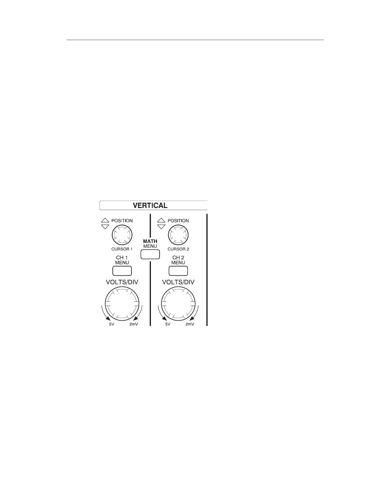
Controls for adjusting vertical scale, position, and input parameters.
Controls for adjusting horizontal scale and position of waveforms.
Controls for setting up trigger parameters like level and holdoff.
Overview of front-panel buttons for accessing menus and functions.
Description of the oscilloscope's input and output connectors.
Steps to quickly display and measure signal amplitude, frequency, and period.
How to use the Measure menu for automated signal measurements.
Procedure to measure two signals and calculate amplifier gain.
Using video triggers for stable display of video output signals.
How to trigger on video fields for a stable display.
How to trigger on specific video lines for detailed analysis.
Examining specific waveform portions without changing the main display.
Setting holdoff to lock onto odd or even video fields for stable display.
Setting up the oscilloscope to capture single events like relay operations.
Using math functions to analyze differential signals.
Evaluating circuit impedance changes with temperature using XY mode.
Setting acquisition parameters like mode, rate, and averages.
Automatically adjusting controls for a usable input signal display.
Displaying measurement cursors and using the cursor menu.
Changing waveform presentation and display appearance.
Adjusting horizontal scale, position, and time base.
Performing waveform math operations like addition and subtraction.
Accessing automated measurement capabilities for signals.
Saving and recalling instrument setups and waveforms.
Setting trigger parameters like type, source, mode, coupling, and holdoff.
Accessing utility menus for system status, self calibration, and language.
Adjusting vertical scale, position, and input parameters for each channel.
Specifications related to acquisition modes and rates.
Specifications for input coupling and impedance.
Specifications for digitizers, voltage/division, and bandwidth.
Specifications for the P2100 passive probe.
Specifications for sample rate, record length, and time base.
Specifications for trigger sensitivity, level, and types.
Specifications for cursors and automated measurements.
Specifications for the oscilloscope display type, resolution, and contrast.
Specifications for the probe compensator output voltage and frequency.
Specifications for source voltage, power consumption, and fuse.
Operating and non-operating environmental conditions.
Specifications related to size and weight.
Information on safety certifications and regulatory compliances.
List of standard accessories included with the oscilloscope.
List of optional accessories available for purchase.
Guidelines for general care and storage of the instrument.
Procedures for cleaning the instrument and probes safely.


