Performance Tests
TDS7104 & TDS7054 Service Manual
4-51
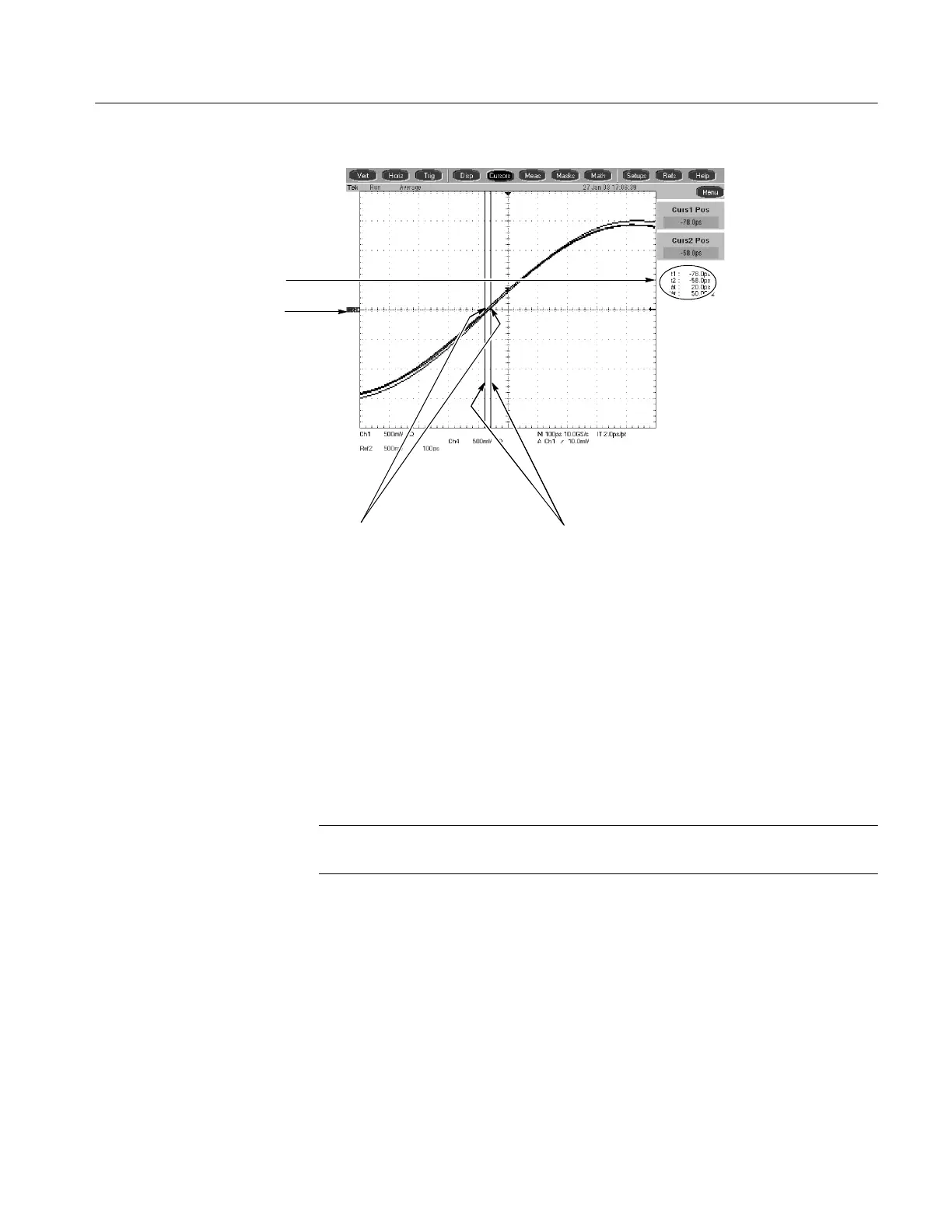
Locate the time reference
points for these waveforms
2
Display the waveforms
1
Read results
4
Align each cursor to the time
reference points
3
Figure 4- 22: Measurement of channel delay
g. Check against limits: Use the cursors to measure the skew from C H 1 to
CH2,CH1toCH3,andCH1toCH4.Writedownthesethree
numbers in the first measurement column of Table 4--8. Note that these
numbers may be either positive or negative.
h. Move the power divider on CH 1 to CH 2. Move the power divider on
CH4toCH1.
NOTE. To eliminate errors caused by the cables, the measurements are repeated
and averaged after swapping the channel position of the cables.
i. Repeat the procedure from step 1.c through 2.e.
j. Again use the cursors to measure the skew from CH 1 to C H 2, CH 1 to
CH 3, and CH 1 to CH 4. Write down these numbers in the second
measurement column of Table 4--8. Note that these numbers may be
either positive or negative.
k. Add the first CH 1 to CH 2 skew measurement to the second CH 1 to
CH 2 skew measurement and divide the result by 2. Use Table 4--8.
 Loading...
