Performance Tests — Semi-Automated Method
4-24
TDS7104 & TDS7054 Service Manual
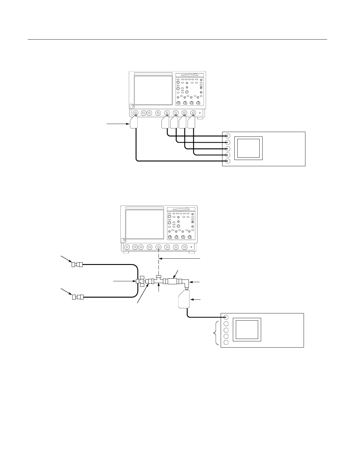
Fluke 9500B
Connect Fluke 9520 or 9530 output
modules to oscilloscope CH1 through
CH 4 inputs and AUX IN as shown
TDS7000 oscilloscope
Figure 4- 9: Setup to check delay between channels
Fluke 9500B
20I 50 Ω cable
SMA female
short
BNC T
connector
BNC 90° female to
male adapter
SMA T connector
SMA female
short
BNC to SMA
adapter
2X attenuator
TDS7000 oscilloscope
Leave unused output
modules (not shown)
connected to Fluke 9500B
Fluke 9520 output module
Connect BNC T to oscilloscope CH 1
20I 50 Ω cable
Figure 4- 10: Setup to check delta t ime accuracy
 Loading...
