Brief Procedures
4-8
TDS7104 & TDS7054 Service Manual
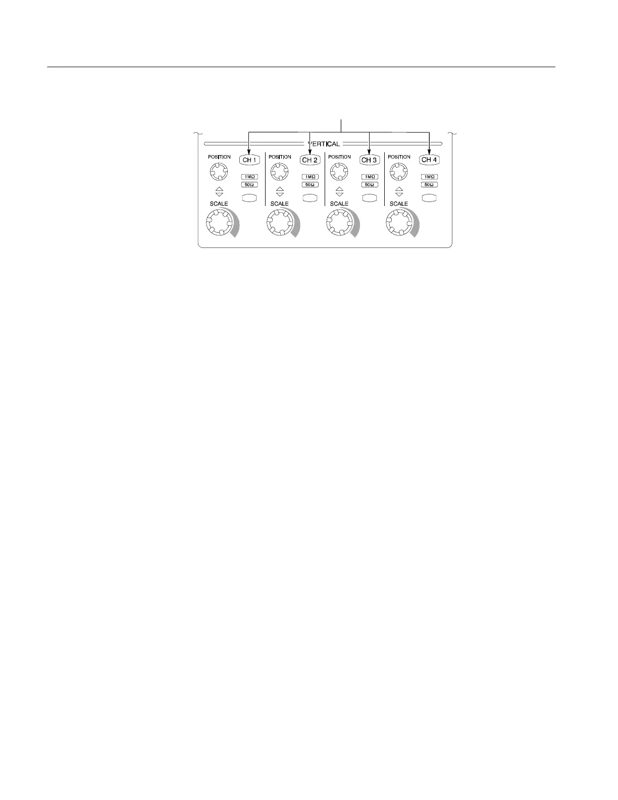
Channel buttons
Figure 4- 3: Channel button location
4. Select the channel to test: Push the channel button for the channel you are
currently testing. The button lights and the channel display comes on.
5. Set up the oscilloscope: Push the front panel AUTOSET button. This sets
the horizontal and vertical scale for a usable display and sets the trigger
source to the channel you are testing.
6. Verify that the channel is operational: Confirm that the following statements
are true.
H The vertical scale readout for the channel under test shows a setting of
500 mV, and a square-wave probe-compensation signal is displayed
on-screen.
H The front-panel vertical POSITION knob (for the channel you are
testing) moves the signal up and down the screen when rotated.
H Turning the vertical SCALE knob counterclockwise (for the channel you
are testing) decreases the amplitude of the waveform on-screen, turning
the knob clockwise increases the amplitude, and returning the knob to
500 mV returns the amplitude to about 2 divisions.
7. Verify that the channel acquires in all acquisition modes: Pull down the
Horiz/Acq menu to select Horizontal/Acquisition Setup. . . . Click the
Acquisition tab in the control window that displays. Click each of the five
acquisition modes and confirm that the following statements are true.
H Sample mode displays an actively acquiring waveform on-screen. (Note
that there is a small amount of noise present on the square wave).
H Peak Detect mode displays an actively acquiring waveform on-screen
with the noise present in Sample mode “peak detected.”
H Hi Res mode displays an actively acquiring waveform on-screen with the
noise that was present in Sample mode reduced.
 Loading...
