Adjustment Procedures
5-4
TDS7104 & TDS7054 Service Manual
Instrumentation Setup
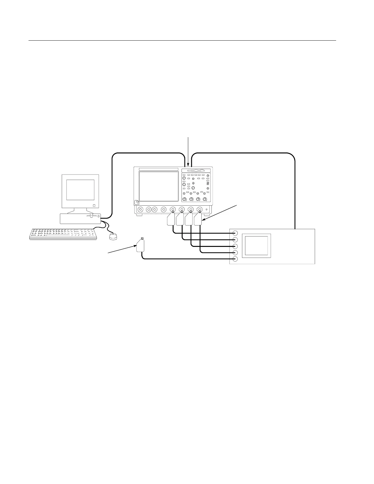
Before you can execute the adjustment program, you need to set up and
configure the instrumentation. Make connections according to the following
diagrams. If you are using a separate computer as the controller, see Figure 5--1.
If you are using the oscilloscope as a controller, see Figure 5--2.
Fluke 9500B
Controller
Oscilloscope
GPIB cableGPIB cable
GPIB cables daisy chained onto
the oscilloscope GPIB connector
Connecting the fifth output module to
the oscilloscope is only required when
prompted to connect the head by the
adjustment program
Connect Fluke 9520 or
9530 output modules
to the oscilloscope
CH1 through CH 4
inputs as shown
Figure 5- 1: Adjustment setup using a separate controller
 Loading...
