Brief Procedures
4-12
TDS7104 & TDS7054 Service Manual
Equipment
required
One BNC cable, such as Tektronix part number 012-0076-00
Prerequisites None
1. Initialize the oscilloscope: Push the front-panel DEFAULT SETUP button.
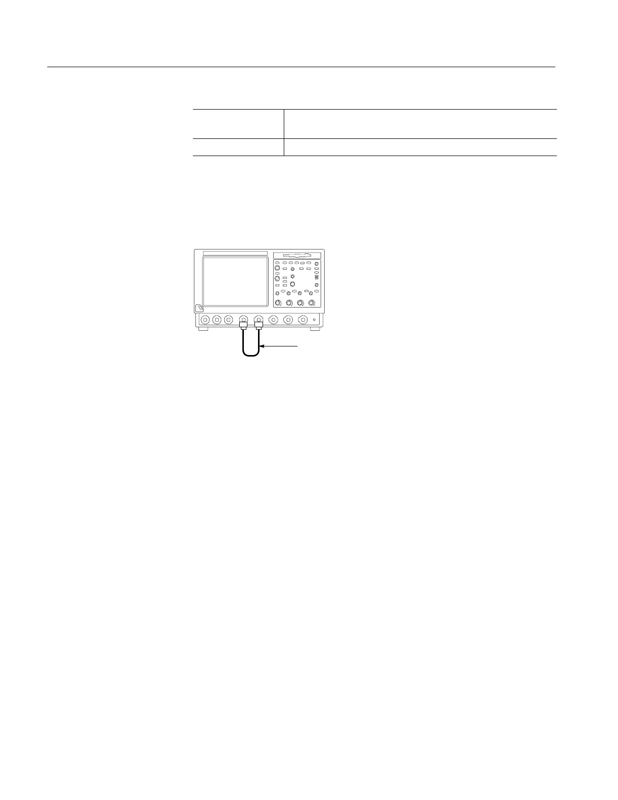
2. Hook up the signal source: Connect the BNC cable from the probe com-
pensation output to the CH 1 input as shown in Figure 4--5.
TDS7000 oscilloscope
BNC cable from PROBE
COMPENSATION output to
CH 1 input
Figure 4- 5: Setup for trigger test
3. Set up the oscilloscope: Push the front-panel AUTOSET button.
4. Verify that the main trigger system operates: Confirm that the following
statements are true.
H The trigger level readout for the A (main) trigger system changes with
the trigger-LEVEL knob.
H The trigger-LEVEL knob can trigger and untrigger the square-wave
signal as you rotate it. (Leave the signal untriggered).
H Pushing the front-panel trigger LEVEL knob sets the trigger level to the
50% amplitude point of the signal and triggers the signal that you just
left untriggered. (Leave the signal triggered. )
Verify the A (Main) and B
(Delayed) Trigger Systems
 Loading...
