Brief Procedures
4-10
TDS7104 & TDS7054 Service Manual
Equipment
required
One BNC cable, such as Tektronix part number 012-0076-00
Prerequisites None
1. Initialize the oscilloscope:Push the front-panel DEFAULT SETUP button.
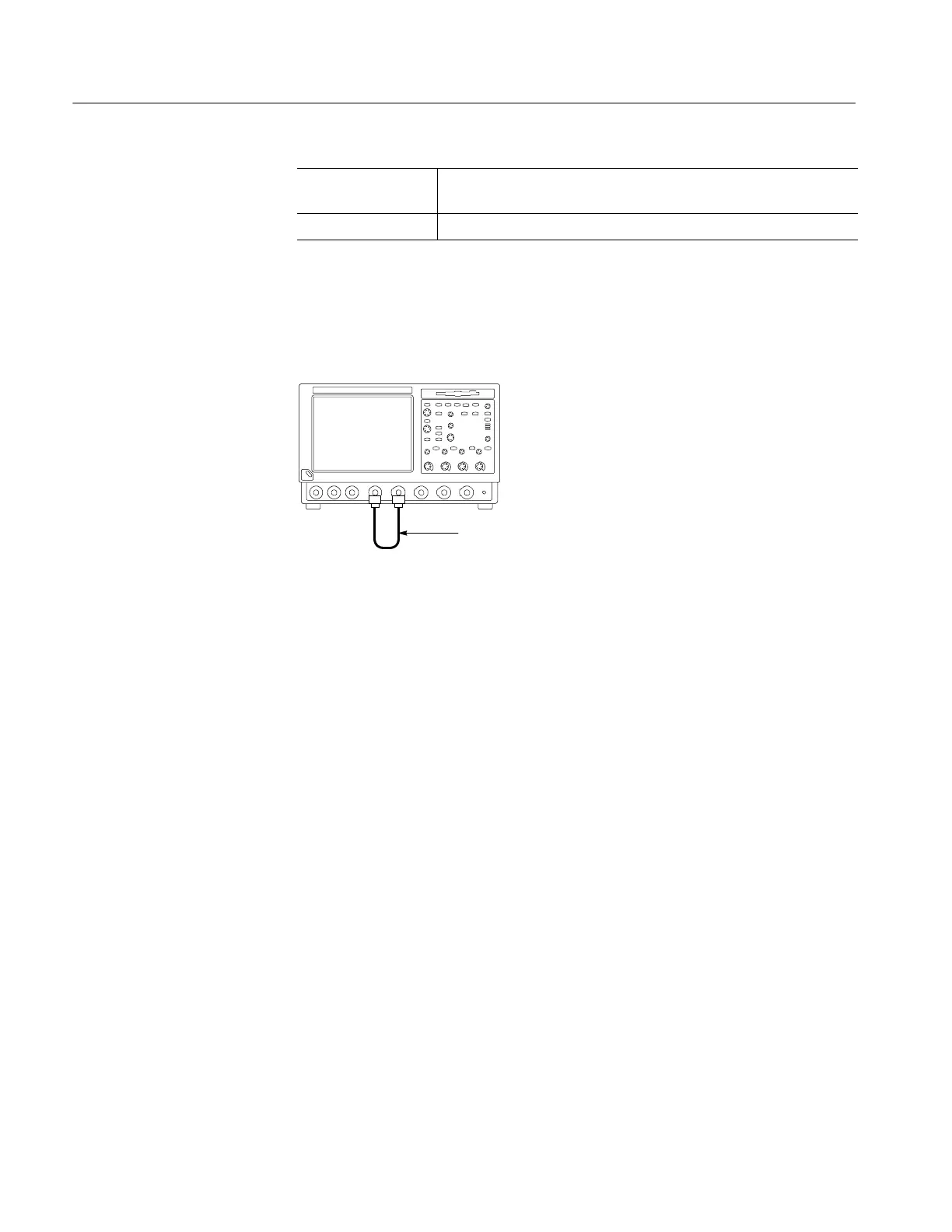
2. Hook up the signal source: Connect the BNC cable from the probe com-
pensation output to the CH 1 input as shown in Figure 4--4.
TDS7000 oscilloscope
BNC cable from PROBE
COMPENSATION output to
CH 1 input
Figure 4- 4: Setup for time base test
3. Set up the oscilloscope: Push the front panel AUTOSET button.
4. Set the time base: Set the horizontal SCALE to 200 s/div. The time-base
readout is displayed at the bottom of the graticule.
5. Verify that the time base operates: Confirm the following statements.
H One period of the square-wave probe-compensation signal is about five
horizontal divisions on-screen for the 200 s/div horizontal scale setting.
H Rotating the horizontal SCALE knob clockwise expands the waveform
on-screen (more horizontal divisions per waveform period), counter-
clockwise rotation contracts it, and returning the horizontal scale to
200 s/div returns the period to about five divisions.
H The horizontal POSITION knob positions the signal left and right
on-screen when rotated.
6. Verify horizontal delay:
a. Center a rising edge on screen:
H Set the horizontal POSITION knob so that the rising edge where the
waveform is triggered is lined up with the center horizontal
graticule.
Verify the Time Base
 Loading...
