Specifications
1-16
TDS7104 & TDS7054 Service Manual
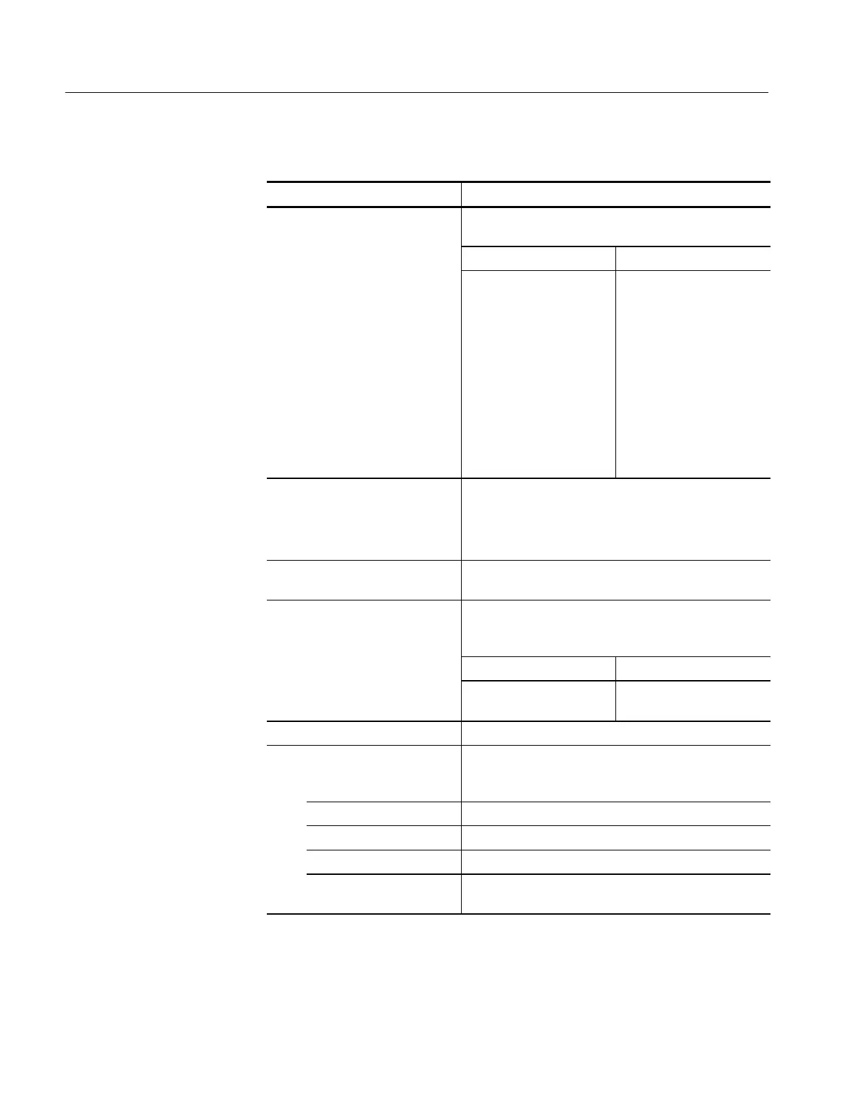
Table 1- 6: Input/output port specifications
Characteristic Description
n Probe Compensator Output Front-panel BNC connector, requires Probe Cal Deskew
Fixture for probe attachment
Output voltage Frequency
1.0 V (from base to top) ±
1.0% into a ≥ 50 Ω load
Note: During probe calibra-
tion only, a relay switches a
DC cal ibration voltage to
this output in place of the
1kHz square wave. This
voltage varies from --10 V
to+10Vwithasource
impedance less than 1 W
and short circuit current as
high as 300 mA.
1 kHz ± 5%
n Anal og Signal Output amplitude Front-panel BNC connector, provides a buffered version of
the signal that is attached to the channel 3 input
20 mV/div ± 20%intoa1MΩ load
10 mV/div ± 20% into a 50 Ω load
Analog Signal Output bandwidth,
typical
100 M Hz into a 50 Ω load
n Auxiliary Output levels Front -panel BNC connector, provides a TTL-compatible
pulse (polarity selectable) for each A or B trigger
(selectabl e)
V
out
high V
out
low (true)
≥2.5 V int o open circuit,
≥1.0 V into 50 Ω l oad
≤0.7 V wit h ≤4masink,
≤0.25 V into 50 Ω l oad
Auxiliary Output pulse width, typical Pulse width varies, 1 s minimum
External reference Run SPC whenever the external reference is more than
2000 ppm different than the internal reference or the
reference at which SPC was last run.
Frequency range 9.8 MHz to 10.2 MHz.
n I nput sensi tivity ≥200 m V
p-p
Input volt age, maximum 7V
p-p
Input impedance 1.5 kΩ, 40 pF. Measure impedance at >100 kHz to make
the blocking capacitor i nvisible
 Loading...
