Troubleshooting
TDS7104 & TDS7054 Service Manual
6-- 71
Table 6--13: Diagnostic LED (Cont.)
LED
Diagnostic status
LED
Test methodTestingPassed test
P Loading files from host Program has connected to host and is loading oscilloscope
files.
— Load process complete Files have completed loading.
Troubleshooting Using Reset Circuits
The Power PC (PPC) board uses a combination of removable jumpers and
surface mount resistors to manipulate circuit reset for troubleshooting.
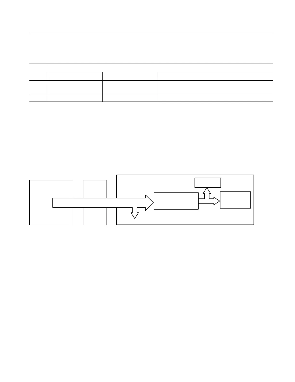
There are three PCI busses on the PPC board, the NLX primary PCI bus, L2 PCI
bus, and the embedded PPC PCI bus. A hardware fault on any of these busses
can prevent Windows from starting properly.
C&T 6900 Video Adapter
Bus 0 J841
J840
Bus 1
RiserNLX (Windows)
PPC (Oscilloscope)
NLX Primary PCI Bus
Transparent Bridge
Bridge
PCMCIA
PCMCIA
Figure 6--34: The three PCI busses
Using jumpers J840 and J841 (see Figure 6--36 on page 6--73) you can selectively
remove components from the NLX primary PCI bus. This is useful when
Windows will not start. The PPC board components on the NLX primary PCI bus
are the DIGITAL 21150 transparent bridge, and the C&T 6900 video adapter.
Installing J840 forces the transparent bridge, all components on the L2 PCI bus,
and all components on the PPC PCI bus into reset. If this allows Windows to
start, you will need to eliminate the PPC PCI bus. The easiest way to force the
PPC PCI bus into reset is to press and hold the PPC reset button, S900. So,
remove J840, and holding the reset button, determine if the instrument will boot
to Windows.
Installing J841 removes the C&T69000 from the Windows side. Note, neither the
PPC ECB VGA port or the LCD will function if J841 is installed. Use the NLX
SVGA port (see Figure 6--35).
 Loading...
