Rev. 000
HYDRAULIC LIFT ASSEMBLY
7-28
TX 413 Service Manual
3. Remove the two hose clamps, located under the
loader arm assembly (Fig. 287).
Figure 287 DSC-1042
10. Start the unit and raise the loader arm. Remove
the jack stand. Continue operating the loader arm
up, down, and tilt to help purge the system of any
air. Check for any oil leaks at the hydraulic hose
connectors. After running the hydraulics, recheck
the oil reservoir; see the Maintenance Section,
Checking the Hydraulic Reservoir, page 3-4. Shut
the engine off.
11. Install the rear cover.
Loader Arm Assembly Removal
1. Remove the rear cover and belt cover.
2. Raise the loader arm assembly to the highest
position and install the cyclinder lock in the
hydraulic lift cylinder (Fig. 286).
Figure 286 DSC-1041
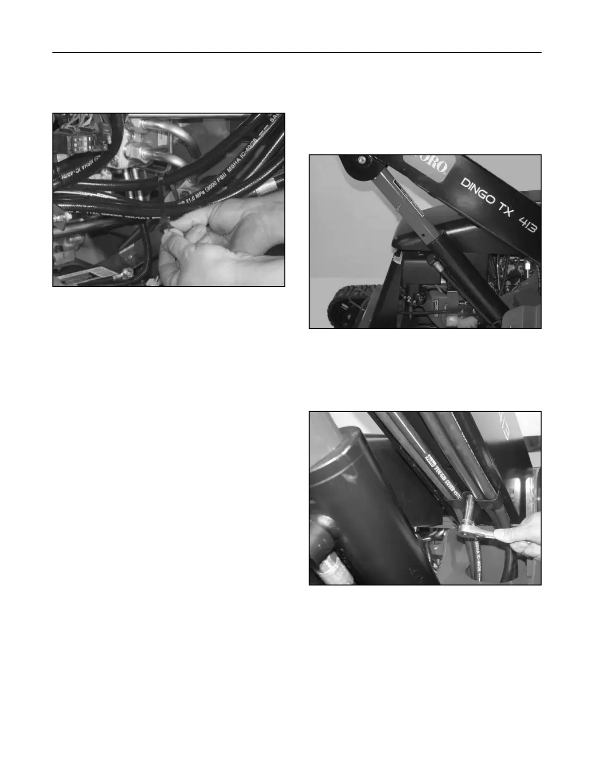
9. Install cable tie strap around all four hydraulic
hoses, approximately 8" (20.32cm) to the right of
the rear clamp (Fig. 285).
Figure 285 DSC-1075

 Loading...


