Rev. 000
DRIVE SYSTEM
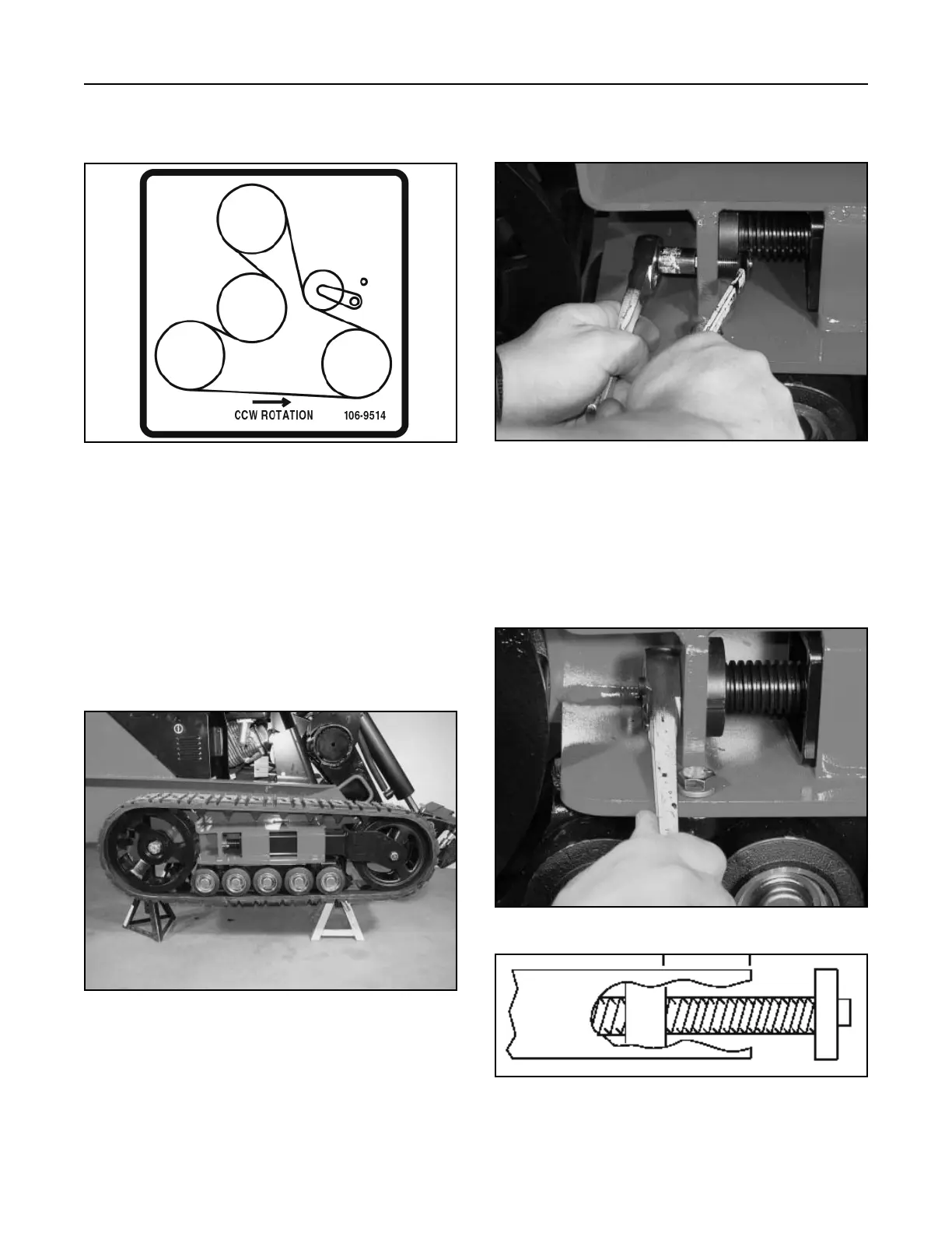
Figure 426 106-9514 decal
Figure 428 DSC-0793
Figure 427 DSC-0791
Figure 429 DSC-0794
8-4
TX 413 Service Manual
3. Check belt routing, (Fig. 426). Start unit to make
sure the belt is operating properly.
2. Remove the bolt and nut securing the tensioner
bolt (Fig. 428).
Track Removal
1. Raise and securely support the side of the unit to
be worked on so that the track is 3 to 4” (7.6 to
10cm.) off the ground (Fig. 427).
3. Using a 1/2” drive socket ratchet, release the
drive tension by turning the tensioner bolt
clockwise until the tensioning nut contacts the
tensioner bolt head. Push the tension wheel
toward the rear of the unit (Fig. 429 and Fig 430).
4. Install drive belt cover with retaining knob, the
pulley cover with two bolts, and the rear cover.
Figure 430 track install #3

 Loading...


