Rev. 000
TX 413 Service Manual
6-17
HYDRAULIC SYSTEM
11. Install drive belt; refer to Drive Belt Installation
section on page 8-3.
12. Install battery and battery cables.
13. Follow the Purging Air Procedures; refer to the
Purging Air Procedures section on page 6-4.
14. Check all the hydraulic line connections for any
leaks.
15. Check the traction control for neutral; refer to
Traction Control Neutral Position section on page
6-5.
16. Check the traction unit for tracking. If adjustment
is needed, refer to the Adjusting the Tracking
of the Traction Control, Full Forward Position
section on page 6-4.
17. Install the drive belt cover and rear cover. Lower
the traction unit to the ground. Operate the unit to
make sure everything is operating properly.
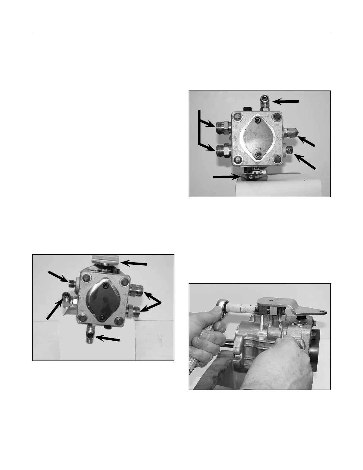
Hydrostatic Pump (Right Drive) Hydraulic
Fitting Orientation
A. Linkage Bracket D. Inlet
B. Wheel Motor E. Bypass
C. Case Drain
Figure 144 DSC-0880
A
B
C
E
D
Hydrostatic Pump (Left Drive) Hydraulic
Fitting Orientation
A. Case Drain D. Linkage Bracket
B. Inlet E. Wheel Motor
C. Bypass
Figure 145 DSC-0899
A
B
C
D
E
Hydrostatic Pump Lever Assembly
Removal and Installation
1. Remove the two retention bolts and nuts holding
the pump lever assembly and the traction clamp
to the trunnion arm of the hydrostatic pump (Fig.
146).
Figure 146 DSC-0881

 Loading...


