Rev. 000
Figure 133 DSC-0896
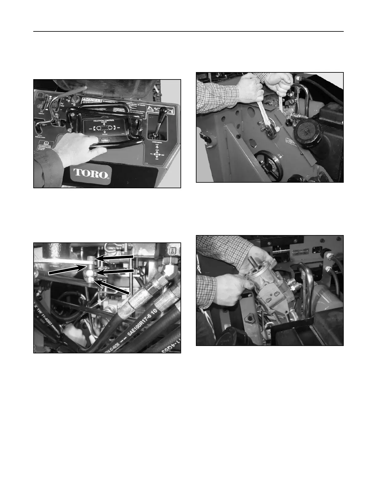
8. Position the control handle so you can install
a 1/4" Allen wrench into the Allen head bolt
retaining the rod linkage spacer to the pump lever
assembly (Fig. 132).
Figure 132 DSC-0874
9. Remove the Allen bolt, spacer, and nut from the
pump lever assembly (Fig. 133).
A
B
D
C
A. Allen head bolt C. Pump lever assembly
B. Linkage spacer D. Nut
HYDRAULIC SYSTEM
6-14
TX 413 Service Manual
11. Lift the hydrostatic pump up and out of the unit
(Fig. 135).
Figure 135 DSC-0898
10. Remove the two mounting bolts and nuts holding
the left drive hydrostatic pump to the frame (Fig.
134).
Figure 134 DSC-0897
Hydrostatic Pump Service
For hydrostatic pump service, refer to Hydro-Gear
BDP-10 service manual (Toro P/N 492-4789).

 Loading...


