Rev. 000
HYDRAULIC LIFT ASSEMBLY
7-60
TX 413 Service Manual
Auxiliary Valve Disassembly and
Assembly
Before disassembly of any hydraulic component, use
a clean, dirt-free work surface and clean solvent to
prevent system contamination (Fig. 403).
2. Remove the spring cap by removing the two hex
head cap screws (Fig. 405).
Figure 403 DSC-1443
Figure 405 DSC-1445
Disassembly
1. Remove the top lever assembly by removing the
two hex head screws (Fig. 404).
3. Remove the spool spring by removing the hex
cap screw. Use a drift punch to hold the top of
the spool (Fig. 406).
Figure 404 DSC-1444
Figure 406 DSC-1446
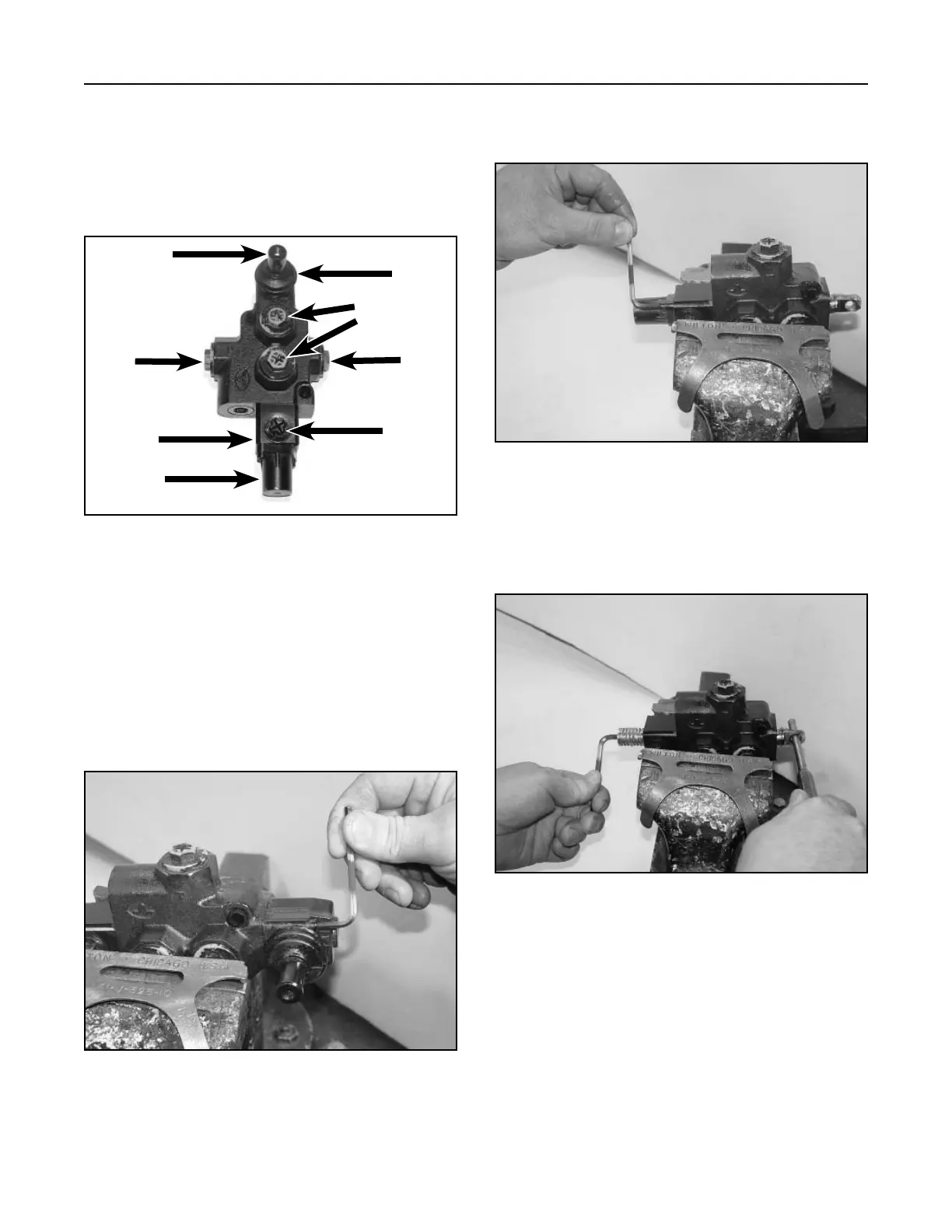
A. Operator lever E. Rubber bellows
B. Inlet F. Return
C. Detent G. Safety switch port
D. Return spring cap
A
B
C
D
E
B
F
G

 Loading...


