Rev. 000
ENGINE
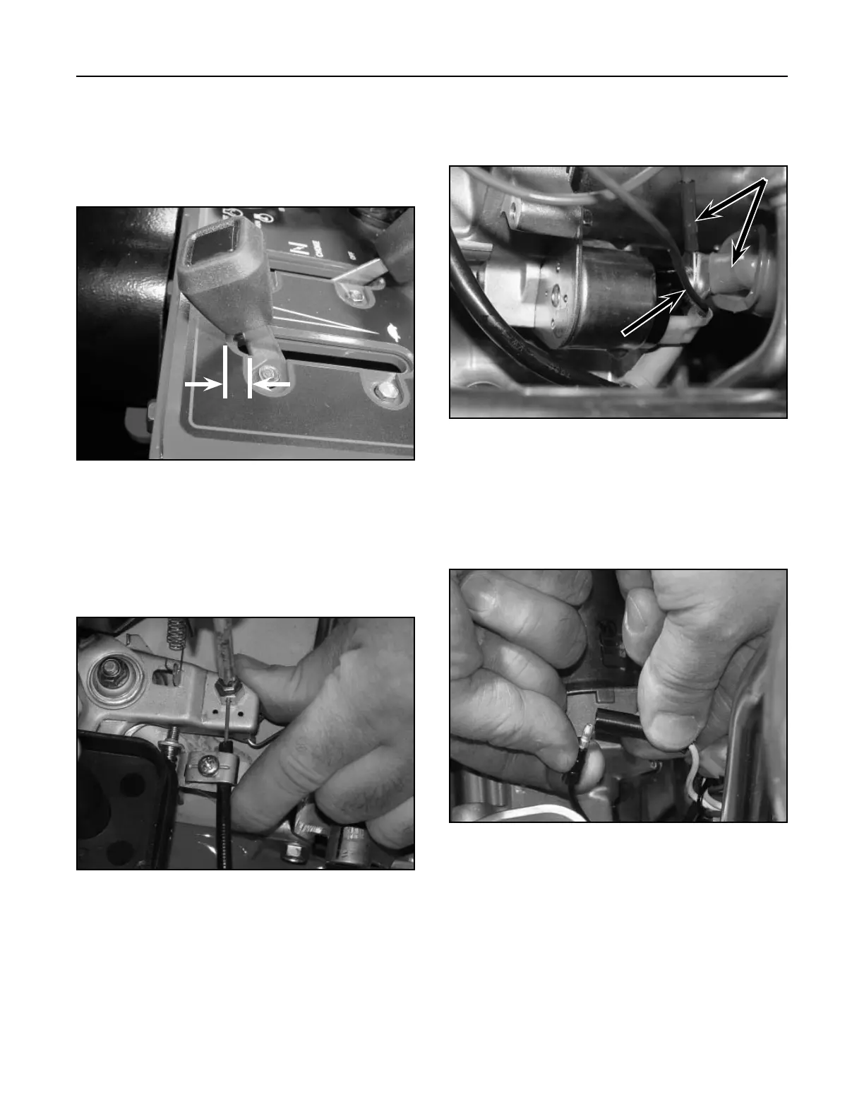
4. Connect the blue wire onto the spade terminal
and the two red wires to the post on the starter
assembly (Fig. 051).
Figure 051 DSC-1111
5. Connect the oil switch, black to white wire (Fig.
052).
Figure 052 DSC-1107
4-10
TX 413 Service Manual
A - Blue wire B - Red wires
A
B
1. Move the throttle control on the dash to full posi-
tion, then back the throttle control so it is approxi-
mately 1/16" (1.6mm) away from the front edge
of the slot (Fig. 049).
Figure 049 DSC-1126
Figure 050 DSC-1127
Throttle Cable Installation
2. On the engine, insert the cable under the clamp;
move the engine throttle lever to the full open
position and hold; tighten the screw on the
throttle lever (Fig. 050).
3. While holding the throttle lever, tighten the
screw/clamp for the cable. Test for proper throttle
control operation.

 Loading...


