Rev. 000
TX 413 Service Manual
6-15
HYDRAULIC SYSTEM
5. Connect and tighten the bottom hydraulic line
(page 6-2, ref 4B) to the wheel motor (Fig. 139).
Figure 139 DSC-0905
4. Connect the case drain hydraulic line to the top
of the pump and hand tighten (page 6-2, Ref. 5)
(Fig. 138).
Figure 138 DSC-0903
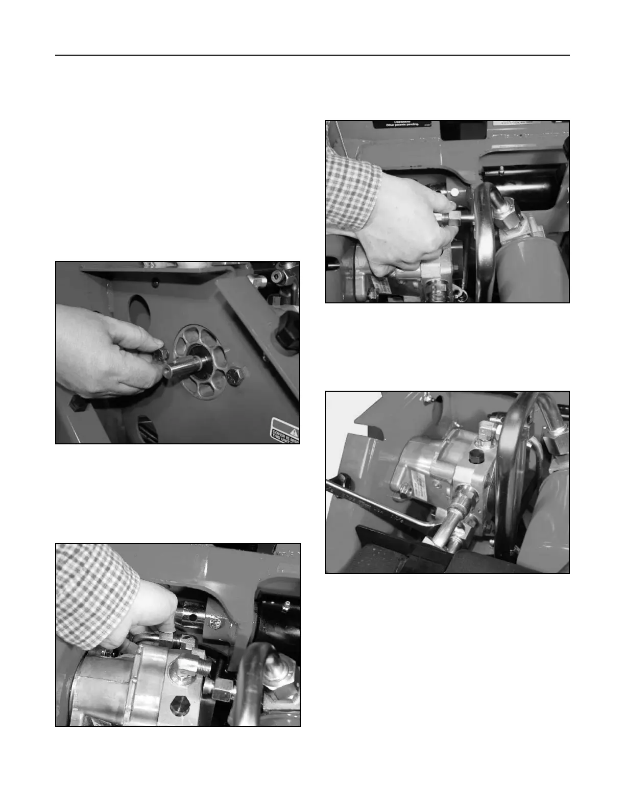
3. Connect the inlet hydraulic line to the side of the
pump and hand tighten (page 6-2, Ref. 7) (Fig.
137).
Figure 137 DSC-0902
Figure 136 DSC-0901
Hydrostatic Pump (Left Drive) Installation
Note: As a reminder, prior to connecting the
hydraulic lines, the O-rings should be
replaced with new ones and lightly
lubricated with petroleum jelly.
1. When installing a new hydraulic pump, make sure
all the hydraulic fittings are installed properly;
refer to the Hydrostatic Pump (Left Drive) Fittings
and Pump Lever Assembly section on pages
6-17.
2. Install the left drive hydrostatic pump with the two
bolts and nuts that retain the pump to the frame.
DO NOT tighten the bolts at this time (Fig. 136).

 Loading...


