Rev. 000
TX 413 Service Manual
7-33
HYDRAULIC LIFT ASSEMBLY
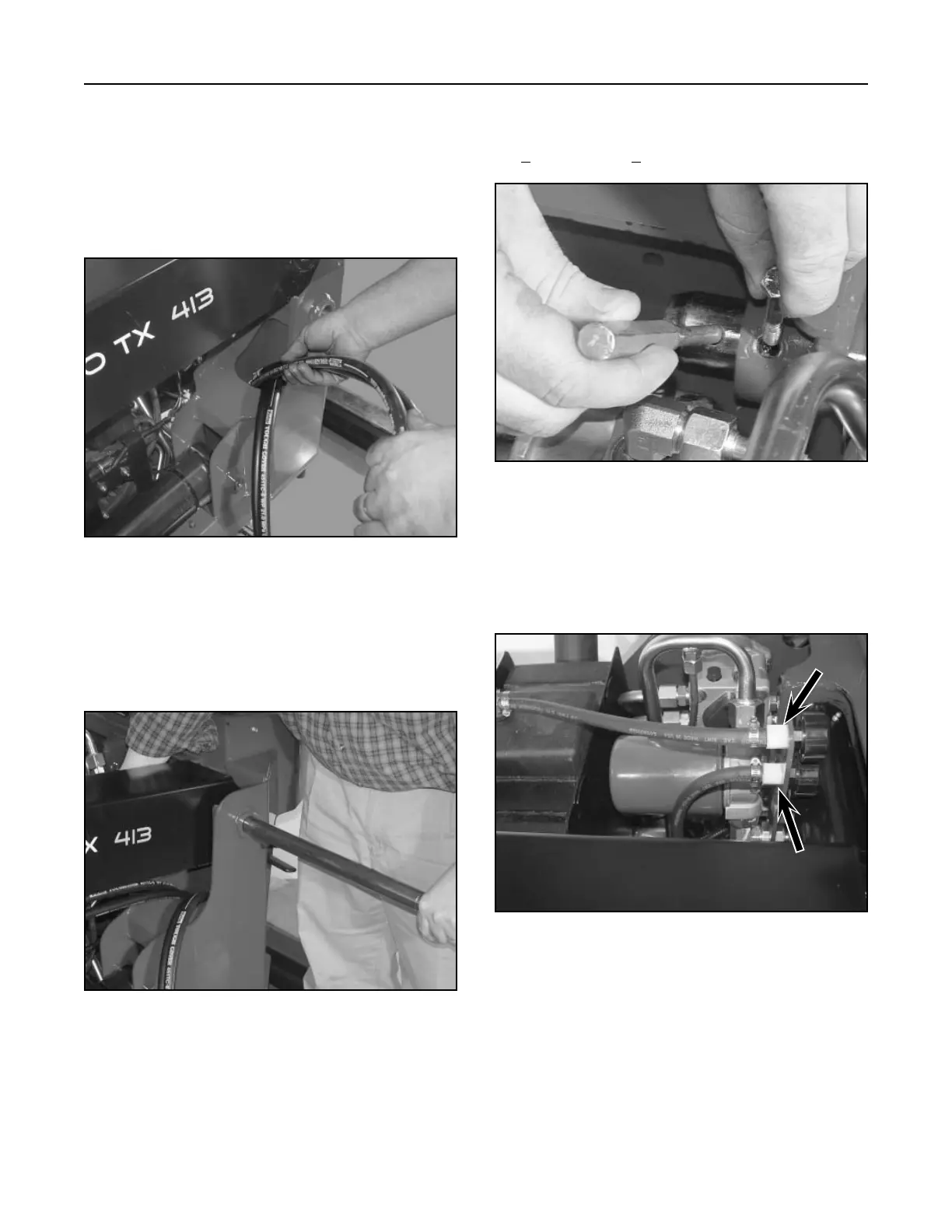
4. Install the two vent hoses, located above the oil
filter bracket. The top vent is for the fuel tank
(A) and the bottom vent is for the hydraulic
reservoir (B) (Fig. 307).
Figure 307 DSC-1064
Loader Arm Assembly Installation
1. Route the tilt cylinder hoses through the opening
of the frame (Fig. 304).
Note: Make sure the hoses are routed to the
inside of the auxiliary hoses that go to the
quick coupler.
3. Use a drift punch in the first hole to align the hole
for the bolt. Install bolt and nut and tighten to 16
+ 2 ft-lbs. (21.7 + 2.7 Nm) (Figure 306).
Figure 304 DSC-1061
Figure 306 DSC-1063
2. Lower the loader arm down into the frame. Apply
a thin layer of grease to the pivot pin and push
the pivot pin through the loader arm assembly
(Fig. 305).
Figure 305 DSC-1062
A
B
Note: Prior to connecting the hydraulic lines,
the o-rings and seals should be replaced
with new ones and lightly lubricated with
petroleum jelly.

 Loading...


