Rev. 000
TX 413 Service Manual
7-49
HYDRAULIC LIFT ASSEMBLY
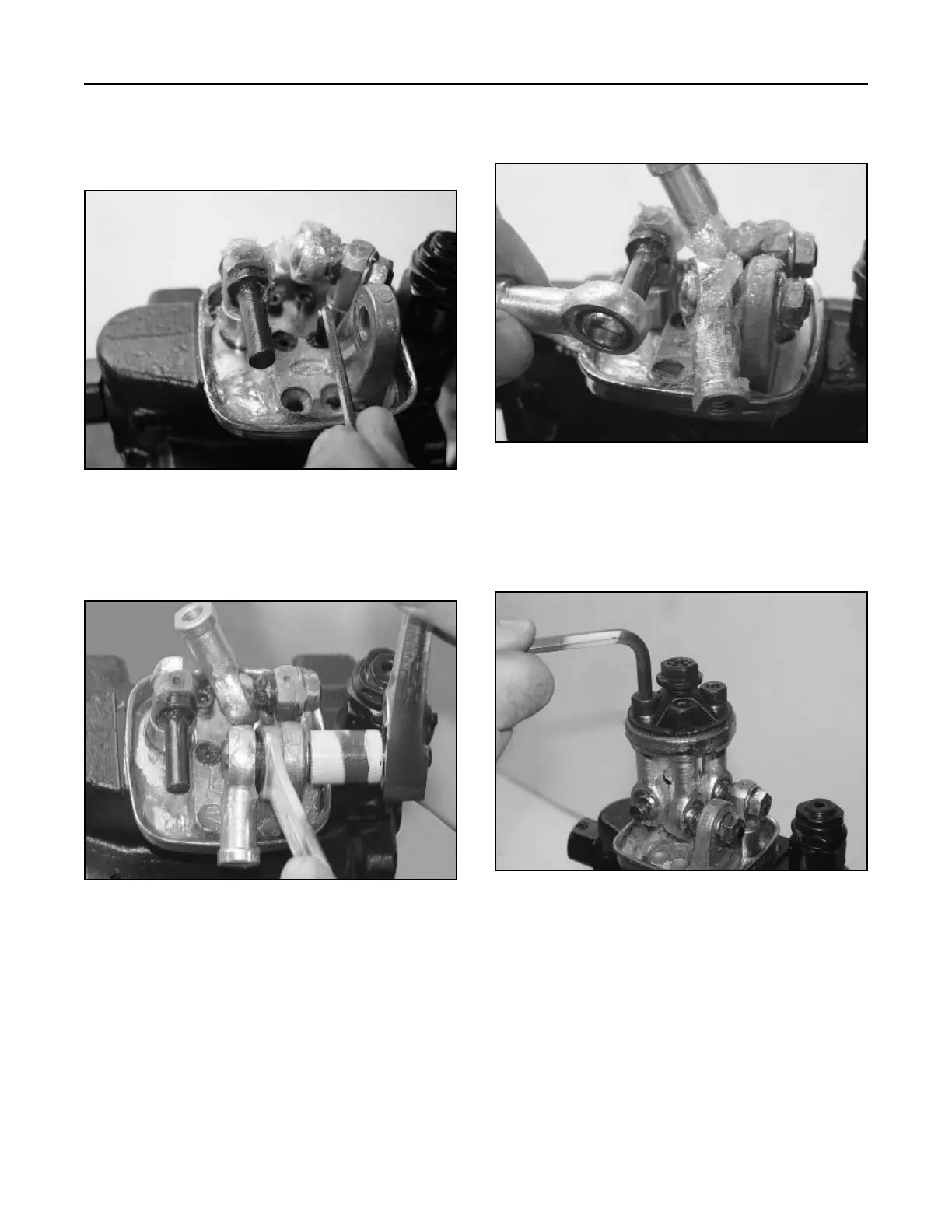
3. Slide the end on the joystick joint onto the
joystick pin for the tilt cylinder (Fig. 362).
Figure 362 DSC-1726
4. Install the articulated holder with 3 hex head
screws and lock washers torque to 17.7 ft.-lbs.
(24 Nm) (Fig. 363).
Figure 363 DSC-1382
2. Install the nut holding the joystick joint to the
pivot for the lift and tilt operation (Fig. 361).
Figure 361 DSC-1395
Joystick Assembly Installation
1. Install the joystick pivot with two hex head screws
(Fig. 360).
Figure 360 DSC-1728

 Loading...


