ATTACHMENTS
10-26 TX 413 Service Manual
Rev. 001
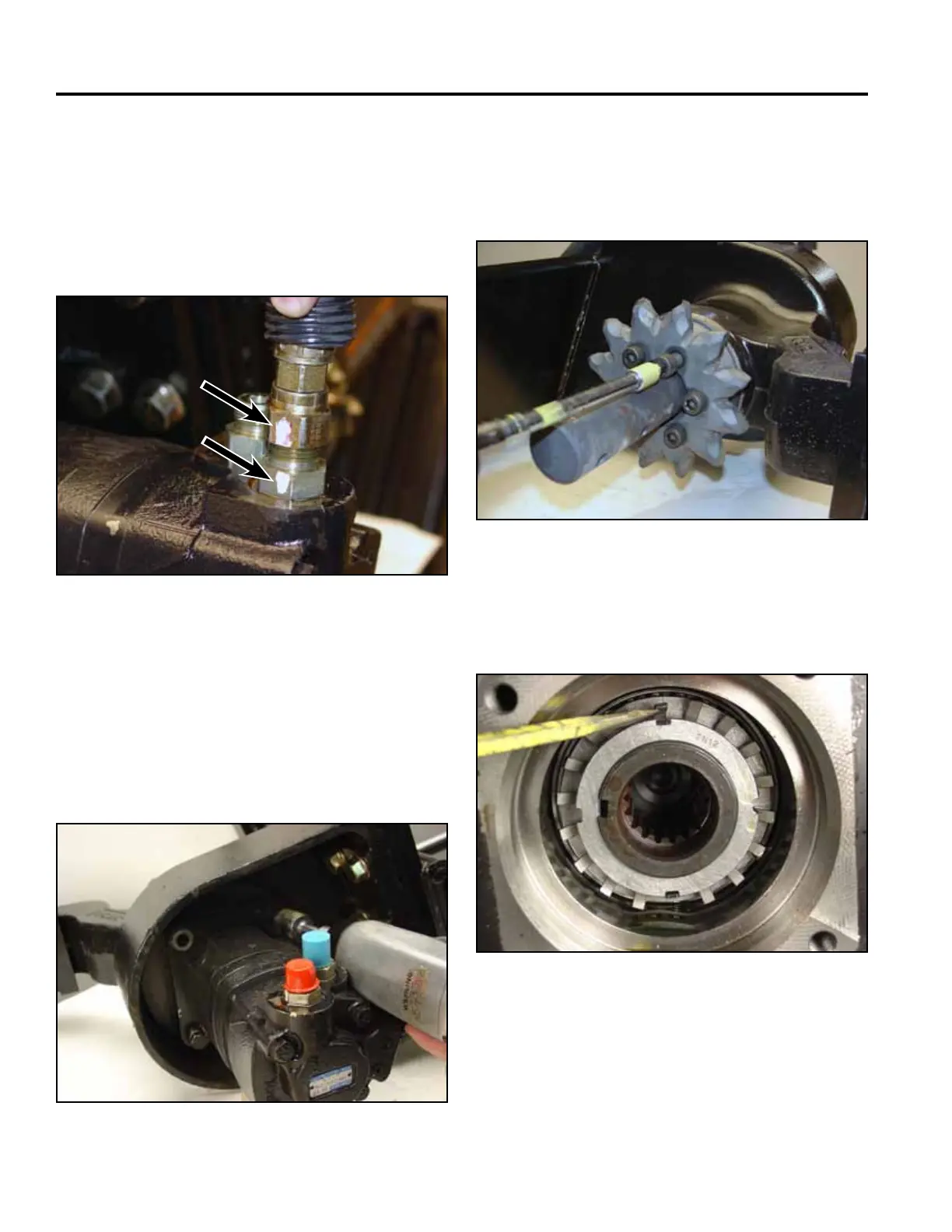
Fig 092 DSC-377
1. Place drain pan under hydraulic motor. Mark one
ttingonthehosetoonettingonthemotor.
Remove hydraulic hoses and cap all motor and hose
ttingstopreventcontaminationtohydraulicsystem
(Fig. 092).
Motor Removal
2. Support the hydraulic motor and remove the four
screws securing the motor to the boom mount.
Note: When removing the hydraulic motor from the
boom mount, hydraulic uid will come out of
the motor as well as the boom mount. Use an
oil pan (Fig. 093).
Fig 093 CLR DSC-0257
2. Bend the two tangs from the bearing lockwasher out
of the bearing locknut (Fig. 095).
Fig 095 CLR DSC-0297
Fig 094 CLR DSC-0252
1. Remove the six hex head screws from the trencher
sprocket (Fig. 094).
Trencher Shaft Removal

 Loading...


