Rev. 000
TX 413 Service Manual
7-39
HYDRAULIC LIFT ASSEMBLY
4. Start the engine and raise the loader arm
assembly to the fully raised position. Remove
the locking arm assembly from the hydraulic lift
cylinder and lower the loader arm assembly to
the floor. Shut the engine off.
Quick Attachment Assembly Installation
1. Align the quick attachment assembly with the
pivot pin holes.
2. Lightly grease pins and install the right and left
pivot pins into the loader arm assembly (Fig. 329).
Figure 329 DSC-1086
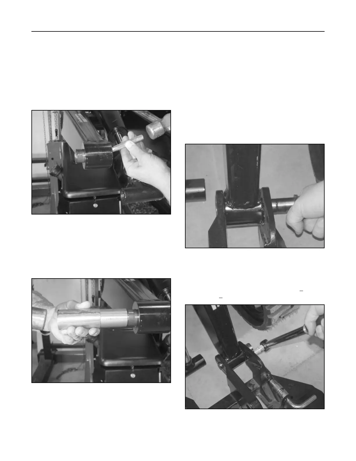
3. Replace the bushings with a driver and drive
the bushings into the loader arm assembly until
they are flush with the outside of loader arm (Fig.
328).
Figure 328 DSC-1085
3. Install the shoulder bolts in both the right and
left pivot pins and torque the bolts to 16 + 2 ft-
lbs.(21.7 + 2.7 Nm) (Fig. 330).
Figure 330 DSC-1087
Loader Arm Bushing Replacement
1. With attach plate removed, raise the loader arm
assembly up to the highest position and install
the cylinder lock in the hydraulic lift cylinder. Shut
the engine off.
2. With a drift punch and hammer, tap the bushing
out of the loader arm assembly; there are two
bushings per pivot pin (Fig. 327).
Figure 327 DSC-1084

 Loading...


