TESTING
9-2
TX 413 Service Manual
Rev. 000
TESTING
9-2
TX 413 Service Manual
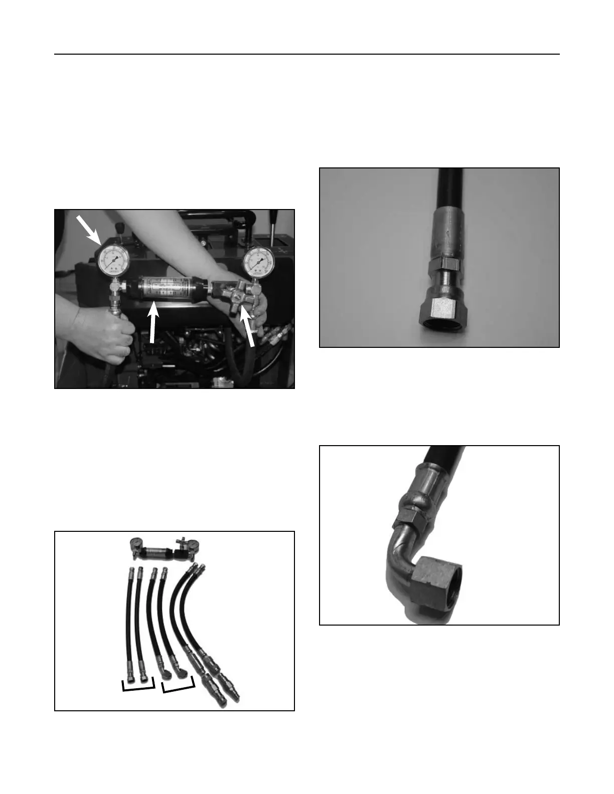
Figure 533 DSC-1516
A
B
C
A. Pressure gauge C. Restriction valve
B. Flow gauge
Due to the many types and manufacturers of test
equipment, the test hoses and fi ttings needed will
vary. Refer to the connection information at each
hydraulic test location.
Hoses being used for pressure and fl ow testing must
exceed maximum system fl ow and pressure and must
be compatible with the type of fl uid in the hydraulic
system (Fig. 533).
Introduction
The three components listed A, B, and C are the
primary testing locations for the TX models (Fig. 534).
Flow Testing Hoses
Figure 534 DSC-0573
Figure 536 DSC-0576
B. LH Drive Hydrostat Pump
Pump Fitting – 1”-14 O-ring Face Seal – 90° Female
(Fig. 536).
Figure 535 DSC-0579
Fitting sizes and test hose confi gurations are also
shown (Fig. 535, 536, 537, 538 and 539).
A. RH Drive Hydrostat Pump
Pump Fitting – 1”-14 O-ring Face Seal - Straight
Female (Fig. 535).
AB
C

 Loading...


