EasyManuals Logo
Home>Toro>Compact Loader>Dingo TX 413

Toro Dingo TX 413 User Manual

Toro Dingo TX 413
244 pages
To Next Page IconTo Next Page
To Previous Page IconTo Previous Page
Page #121 background imageLoading...
Page #121 background image
Rev. 000
HYDRAULIC LIFT ASSEMBLY
7-32
TX 413 Service Manual
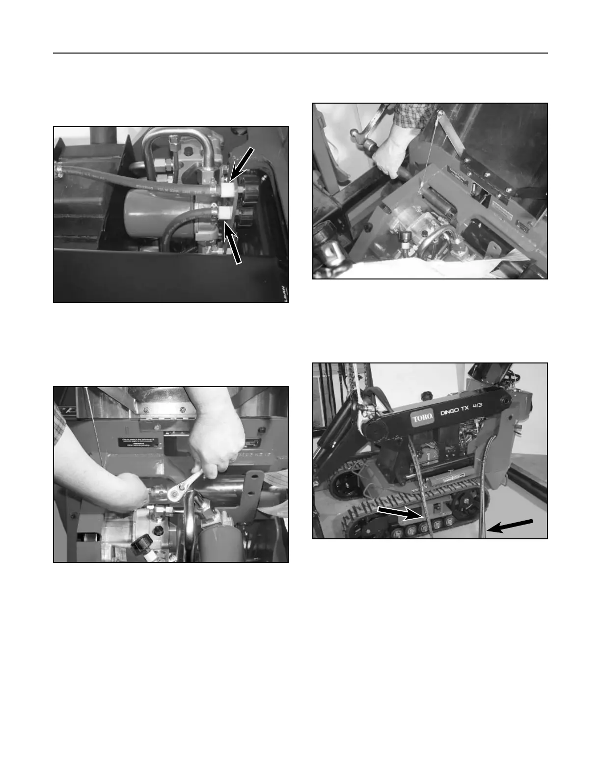
17. Lift the loader arm assembly from the unit (Fig.
303).
Figure 303 DSC-1060
16. With a hammer and a long pipe, tap the pivot pin
out of the loader arm assembly (Fig. 302).
Figure 302 DSC-1058
14. Remove the two vent hoses, located above
the oil filter bracket. The top vent is for the fuel
tank (A) and the bottom vent is for the hydraulic
reservoir tank (B) (Fig. 300).
Figure 300 DSC-1064
15. Remove the bolt and nut at pivot pin for the
loader arm assembly (Fig. 301).
Figure 301 DSC-1057
A
A
B
B
B
A. Tilt cylinder hoses B. Auxiliary hoses
A
A

Table of Contents

Other manuals for Toro Dingo TX 413

Questions and Answers:

Question and Answer IconNeed help?

Do you have a question about the Toro Dingo TX 413 and is the answer not in the manual?

Toro Dingo TX 413 Specifications

General IconGeneral
BrandToro
ModelDingo TX 413
CategoryCompact Loader
LanguageEnglish

Related product manuals