Rev. 000
HYDRAULIC LIFT ASSEMBLY
7-56
TX 413 Service Manual
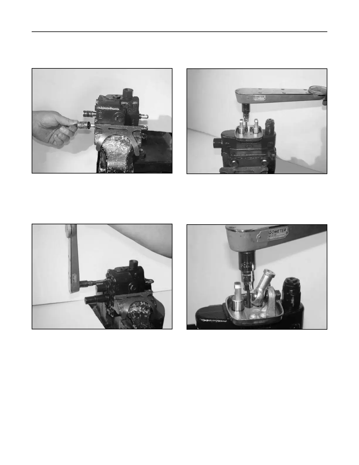
6. Install the detent spring assembly and torque
to 5 ft-lbs. (6.8 Nm). Lubricate the spring with
synthetic base grease grade NLGI2 (Fig. 387).
8. Rotate the valve in the bench vise. Install gasket
and joystick base plate with two cap screws,
torque to 7 ft.lbs. (9.5 Nm) (Fig. 389).
Figure 387 DSC-1420
Figure 389 DSC-1423
7. Install spool caps over the detent and spring
valve. Torque the cap screws to 5 ft. lbs. (6.8
Nm) (Fig. 388).
9. Install the joystick pivot with two cap screws and
torque to 7 ft.lbs (9.5 Nm) (Fig. 390).
Figure 388 DSC-1421
Figure 390 DSC-1425

 Loading...


