Rev. 000
TX 413 Service Manual
8-21
DRIVE SYSTEM
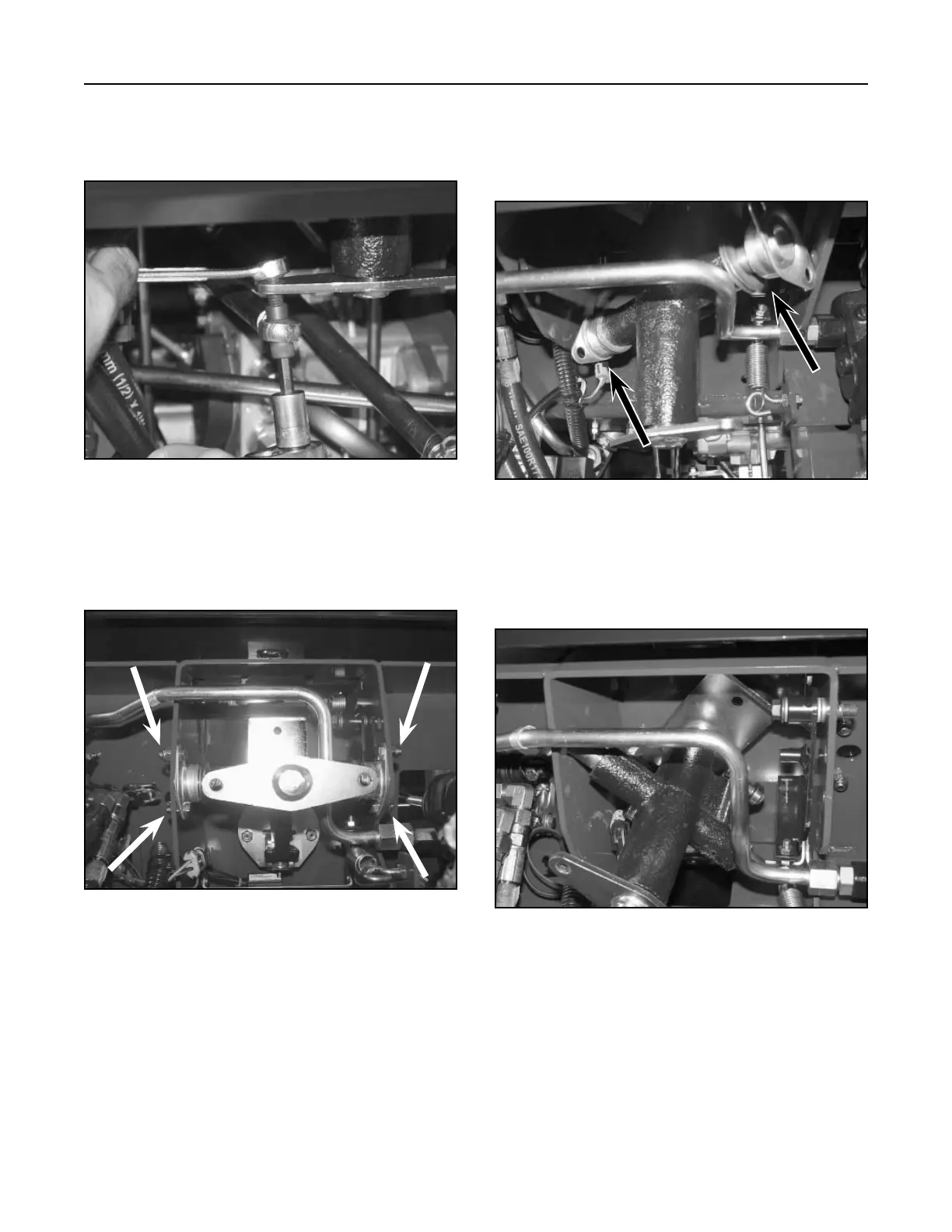
5. Remove four bolts and nuts that retain the
bushings, located on each side of the control
support assembly (Fig. 492).
Figure 492 DSC-1252
4. Disconnect the left side linkage rod by removing
the bolt, spacer, and nut from the rod end bearing
(Fig. 491).
Figure 491 DSC-1263
7. Turn the traction control assembly counter-
clockwise and maneuver the assembly until it
clears the neutral return bracket (Fig. 494).
Figure 494 DSC-1254
6. Turn the traction control assembly clockwise and
remove the bushings, flat washers, and spring
washers from the control support assembly (Fig.
493).
Figure 493 DSC-1253

 Loading...


