ATTACHMENTS
10-6 TX 413 Service Manual
Rev. 001
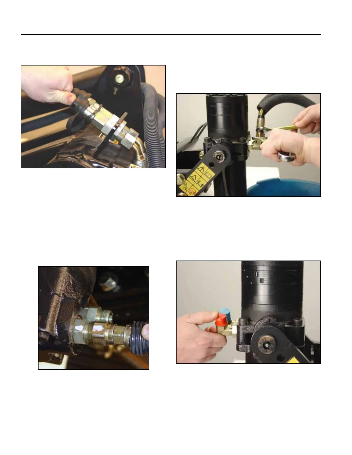
2. Markthehydraulichosettingandmotorttingto
identify their location when reinstalling (Fig. 017).
Note: The hose with the male nipple is on the right
hand side of the power head from operator
position and the hose with the female coupler
is to the left side of the power head from the
operator position.
Fig 017 CLR DSC-0377
3. Placeadrainpanunderhydraulicttingstocatch
hydraulic oil in the lines. Then using a 15/16” wrench
onthehydrauliclinettinganda3/4”openend
wrenchtoholdthemotortting,disconnecthydraulic
lines from the hydraulic motor (Fig. 018).
Fig 018 CLR DSC-0097
Fig 019 CLR DSC-0104
4. Cap the two 90
o
motorttings,aswellastheends
of the hydraulic lines, to prevent contamination (Fig.
019).
Fig 016 CLR DSC-0103
Install dust caps over the ends (Fig. 016).

 Loading...


