Rev. 000
TX 413 Service Manual
7-3
HYDRAULIC LIFT ASSEMBLY
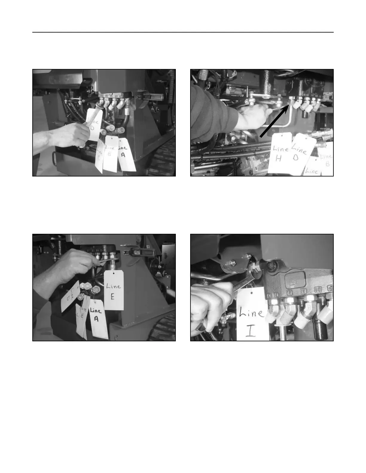
7. (Fig. 191, Ref. H) Remove the hydraulic drain
line from the hydraulic lift valve that goes to the T
fitting on the oil filter base.
Figure 189 DSC-0929
Figure 191 DSC-0933
6. (Fig. 190 Ref. E) With an offset wrench, remove
the hydraulic gear pump hose from the fitting on
the hydraulic lift valve.
8. (Fig. 192, Ref. I) Remove the hydraulic line from
the hydraulic lift valve that goes to the auxiliary
valve.
Figure 190 DSC-0932
Figure 192 DSC-0935
5. (Fig. 189, Ref. D) Remove the second hydraulic
tilt cylinder hose from the fitting at the hydraulic
lift valve.

 Loading...


