TractionLinkageAssembly(continued)
ThetransmissionoftheGroundsmaster360machineconsistsof2pistonpumps.
Theswashplateineachofthepistonpumpsiscontrolledbytheoperatortraction
pedalthroughthetractionlinkageassembly.Correctassemblyofthetraction
linkageassembly(Figure69)isrequiredforpropertractioncircuitoperation.
WhenservicingthetractionlinkageonyourGroundsmaster360machine,use
thefollowinginformation:
Note:RefertotheOperator’sManualforinformationonadjustingtractionpedal
stops,mowspeedlimiterlever,andtractionpedalneutralposition.
1.Thecenterdistancebetweenthetworodends(item41inFigure68)should
be1161mm(45.7inches).Thisisthedistancebetweenthecenterofthe
rodendandthecenteroftherubberbushing(Figure70).T omahhasatool
thatsetsitat1168.4mm(46inches)tobeginandthenitisadjustedoneach
machine.
2.Ifthedualspringhookthatlocatesbehindtheneutralarmspringisremoved,
installthedualspringhooksothatthethreadsextendaftertheangenut
from8.7to9.5mm(0.34to0.37inch)(Figure71).Ifquickerreturntothe
tractionneutralpositionisnecessary,adjustmentcanmadetoincrease
amountofthreadextension.Thisadjustmentwillalsoresultinhigher
pressurerequiredtopressthetractionpedal.
3.Adjustthecontrolarms;refertotheOperator’sManual.
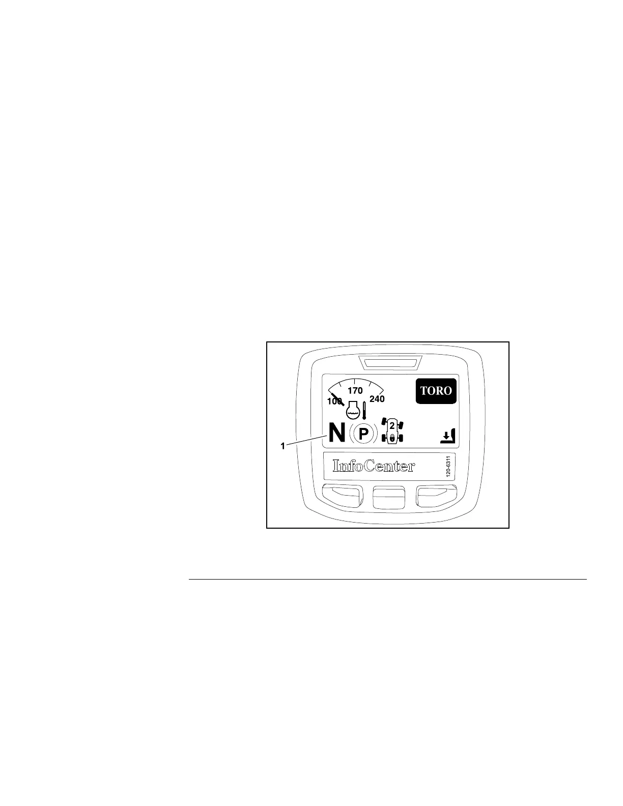
g187656
Figure72
1.Tractionneutralposition
4.Ensurethatthetractionneutralsensorisclosedwhenthetractionpedal
isintheNEUTRALposition:
A.UseInfoCenterdisplaytocheckthetractionneutralsensoroperation
(Figure72).
B.ThetractionneutralsensorLEDshouldbeilluminatedwhenthetraction
pedalisintheNEUTRALposition;refertoTractionNeutralSensor(page
5–43).
5.Afteradjustmentshavebeenmadeandallthetractionlinkagefastenersare
tightened,ensurethatthereisnobindingasthetractionpedalispressed.
ThetractionpedalshouldfreelyreturntotheNEUTRALpositionafteritis
releasedfromeitherforwardorreverse.Also,ensurethatthetractionrod
doesnotcontactanythingthroughbothforwardandreversedirections.
Groundsmaster360
Page4–91
HydraulicSystem:ServiceandRepairs
16225SLRevC

 Loading...