DisassemblingtheFrontSteeringAssembly
g036463
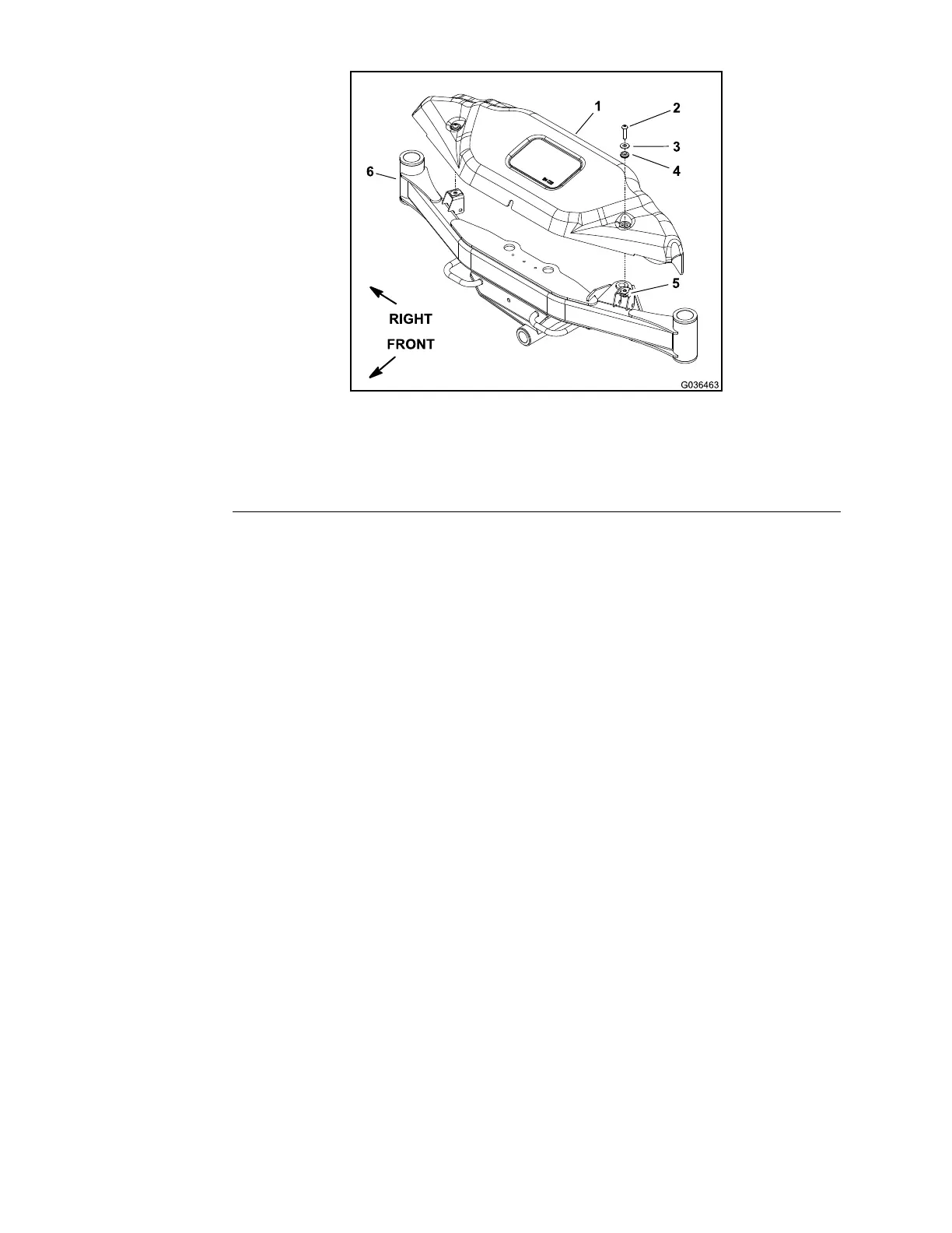
Figure275
1.Frontcover
4.Grommet(2each)
2.Screw(2each)5.Tinnermannut(2each)
3.Flatwasher(2each)
6.Frontaxle
1.Parkthemachineonalevelsurface,lowerthecuttingdeck,shutoffthe
engine,andremovethekeyfromthekeyswitch.
2.Removethefrontcoverfromthefrontaxletogetaccesstothefrontsteering
components(Figure275).
3.Ifnecessary,removethefrontwheel;refertoRemovingtheWheel(page
6–14).
4.Ifnecessary,removethesteeringcylinder;refertoRemovingtheSteering
Cylinder(page4–150).
5.Ifnecessary,removethefrontwheelmotor;refertoRemovingtheFront
WheelMotor(page4–84).
6.Ifnecessary,removethefrontsteeringforkassembly;refertoRemoving
theFrontSteeringFork(page6–28).
7.Removethetierod(item31inFigure274)fromthemachineasfollows:
A.Removethecotterpin(item21inFigure274)andslottedhexnutthat
securetheoutertierodballjointstudtothesteeringfork.
B.Carefullyprytheballjointfromthesteeringforkwithaballjointpicklefork.
C.Loosentheinnertierodendfromthecenterlinkandremovethetierod
fromthemachine.
Note:Theinnerandoutertierodendsarenotavailableseparately.If
wearordamageoccurstothetierodcomponents,replacethetierod
assembly.
8.Removetheadditionalfrontsteeringcomponentsasnecessary(Figure274).
Whenremovingthecenterlink,carefullyprythecenterlinkballjointsfrom
therightandleftarmswithaballjointpicklefork.
9.Iftheangebushings(item12inFigure274)inthefrontaxle,frontaxle
leftarm,orfrontaxlerightarmarewornordamaged,replacetheange
bushings;refertoServicingtheSteeringAssemblyBushings(page6–38).
Chassis:ServiceandRepairs
Page6–32
Groundsmaster360
16225SLRevC

 Loading...