RemovingtheSteeringColumn(continued)
7.Loosenandremovethe3ange-headscrews(item6inFigure282)and
socket-headscrewthatsecurethesteeringcolumntothesteeringcontrol
valve.Notethelocationofthesocket-headscrewfortheassemblypurposes.
8.Slidethesteeringcolumnfromthesteeringcontrolvalveandthemachine.
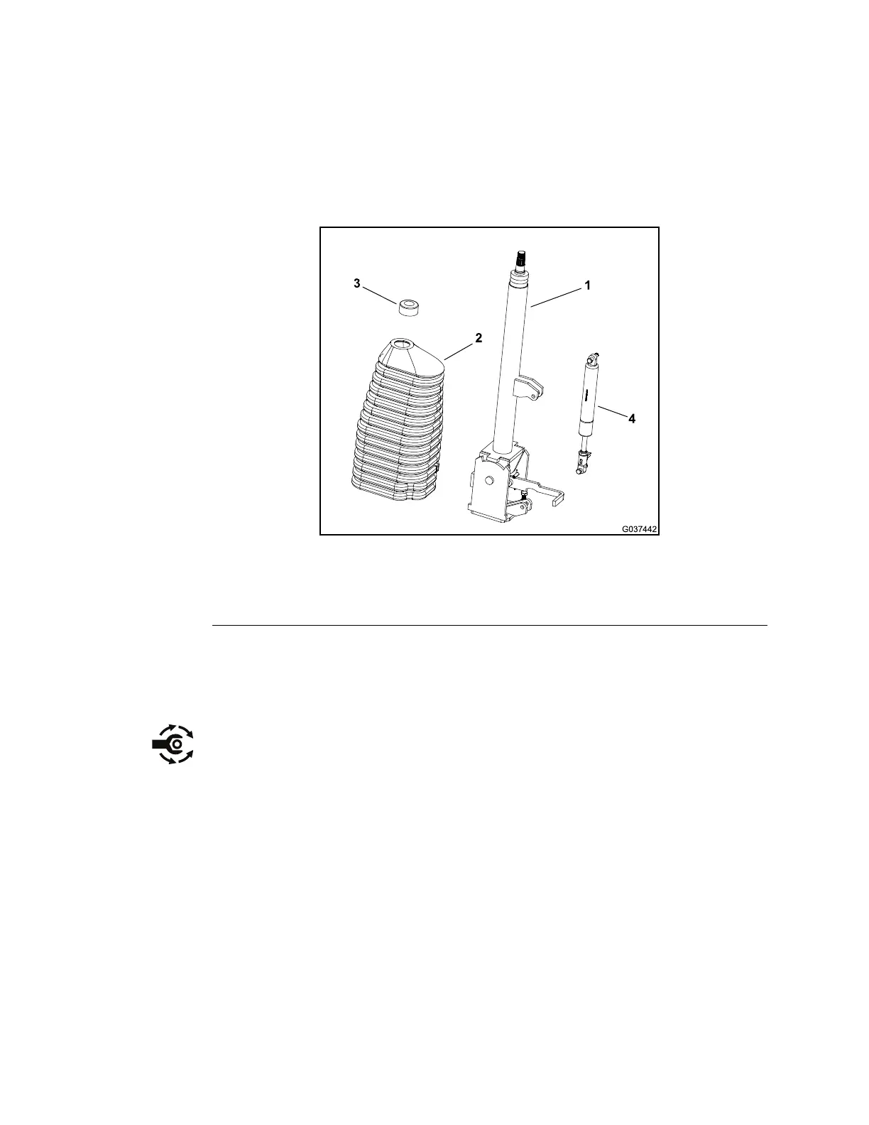
9.Disassemblethesteeringcolumnassemblyasnecessary(Figure283).
InstallingtheSteeringColumn
g037442
Figure283
1.Steeringcolumn
3.Bearing
2.Boot
4.Cylinder
1.Applyanti-seizelubricanttotheinputshaftofthesteeringcontrolvalve(item
7inFigure282).
2.Ensurethatthealignmentbushing(item9inFigure282)ispositionedonthe
steeringcontrolvalveandintotheboreofthesteeringplate.
3.Slidethesteeringcolumnassembly(item1inFigure282)ontothesteering
controlvalve.Securethesteeringcolumninplacewiththe3ange-head
screwsandsocket-headscrew.Tightenthescrewsbyhandandthentorque
thescrewsto47to56N∙m(34to42ft-lb)inacrossingpattern.
4.Slidetherubberbellowstothebottomofthesteeringcolumn.
5.Cleanthetaperedsurfacesofthesteeringwheel(item2inFigure282)and
steeringcolumn.
6.Applyanti-seizelubricanttothesplinesofsteeringcolumnandensureto
keeptheanti-seizelubricantfromthesteeringcolumntaper.Slidethe
steeringwheelontothesteeringcolumn.
7.Securethesteeringwheeltothesteeringcolumnassemblywiththeat
washerandlocknut;torquethelocknutto28to35N∙m(20to26ft-lb).
8.Installthesteeringwheelcover(item4inFigure282)ontothesteeringwheel.
Chassis:ServiceandRepairs
Page6–42
Groundsmaster360
16225SLRevC

 Loading...