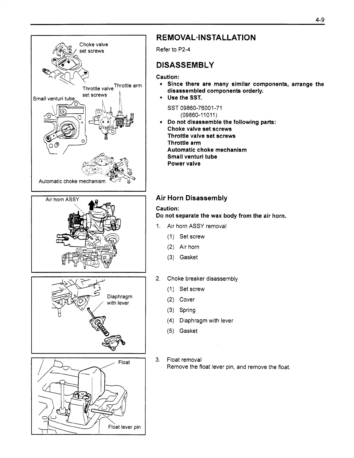
EasyManuals Logo

Toyota 8FGU25 User Manual

Toyota 8FGU25
618 pages
To Next Page IconTo Next Page
To Previous Page IconTo Previous Page
Page #220 background imageLoading...
Page #220 background image
Choke valve
set screws
Throttle arm
Throttle valve
Automatic choke mechanism
Air
t
1
I--,
,
Float
Refer to P2-4
DISASSEMBLY
Caution:
Since there are many similar components, arrange the
disassembled components orderly.
Use the SST.
SST 09860-76001 -71
(09860-11011)
Do not disassemble the following parts:
Choke valve set screws
Throttle valve set screws
Throttle arm
Automatic choke mechanism
Small venturi tube
Power valve
Air
Horn Disassembly
Caution:
Do not separate the wax body from the air horn.
Air horn ASSY removal
(1) Set screw
(2) Air horn
(3) Gasket
Choke breaker disassembly
(1) Set screw
(2)
Cover
(3) Spring
(4)
Diaphragm with lever
(5)
Gasket
Float removal
Remove the float lever pin, and remove the float.
4Y-E Repair
Section 1.1.4

Table of Contents

Other manuals for Toyota 8FGU25

Questions and Answers:

Question and Answer IconNeed help?

Do you have a question about the Toyota 8FGU25 and is the answer not in the manual?

Toyota 8FGU25 Specifications

General IconGeneral
Model8FGU25
Lift Height189 inches
Tire TypePneumatic
TransmissionAutomatic
Engine TypeInternal Combustion
Load Capacity5000 lbs
Fuel TypeGasoline or LPG
Mast Type2-Stage
Overall Width45.3 in (1150 mm)
Wheelbase63 in (1600 mm)

Related product manuals