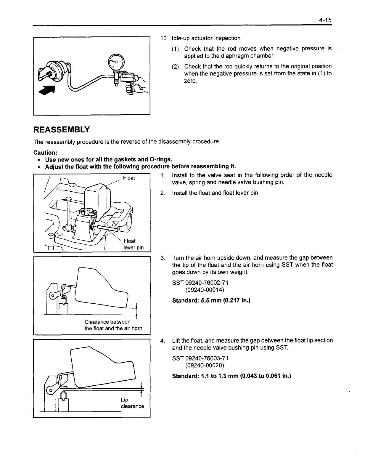
10. Idle-up actuator inspection
(1)
Check that the rod moves when negative pressure is
applied to the diaphragm chamber.
(2) Check that the rod quickly returns to the original position
when the negative pressure is set from the state in
(1) to
zero.
REASSEMBLY
The reassembly procedure is the reverse of the disassembly procedure.
Caution:
Use new ones for all the gaskets and O-rings.
Adjust the float with the following procedure before reassembling it.
pin
Clearance between
the float and the air horn
I
I
(
I
clearance
1.
Install to the valve seat in the following order of the needle
valve, spring and needle valve bushing pin.
2,
Install the float and float lever pin.
3.
Turn the air horn upside down, and measure the gap between
the tip of the float and the air horn using
SST
when the float
goes down by its own weight.
SST 09240-76002-7 1
(09240-0001 4)
Standard:
5.5
mm (0.217 in.)
4. Lift the float, and measure the gap between the float lip section
and the needle valve bushing pin using
SST.
SST
09240-76003-71
(09240-00020)
Standard:
I
.I to 1.3
mm
(0.043 to 0.051 in.)
 Loading...