Marine Installation Manual 2022-03 4-52
4 Ancillary Systems
4.5 Fuel gas system
X62DF-S2.0
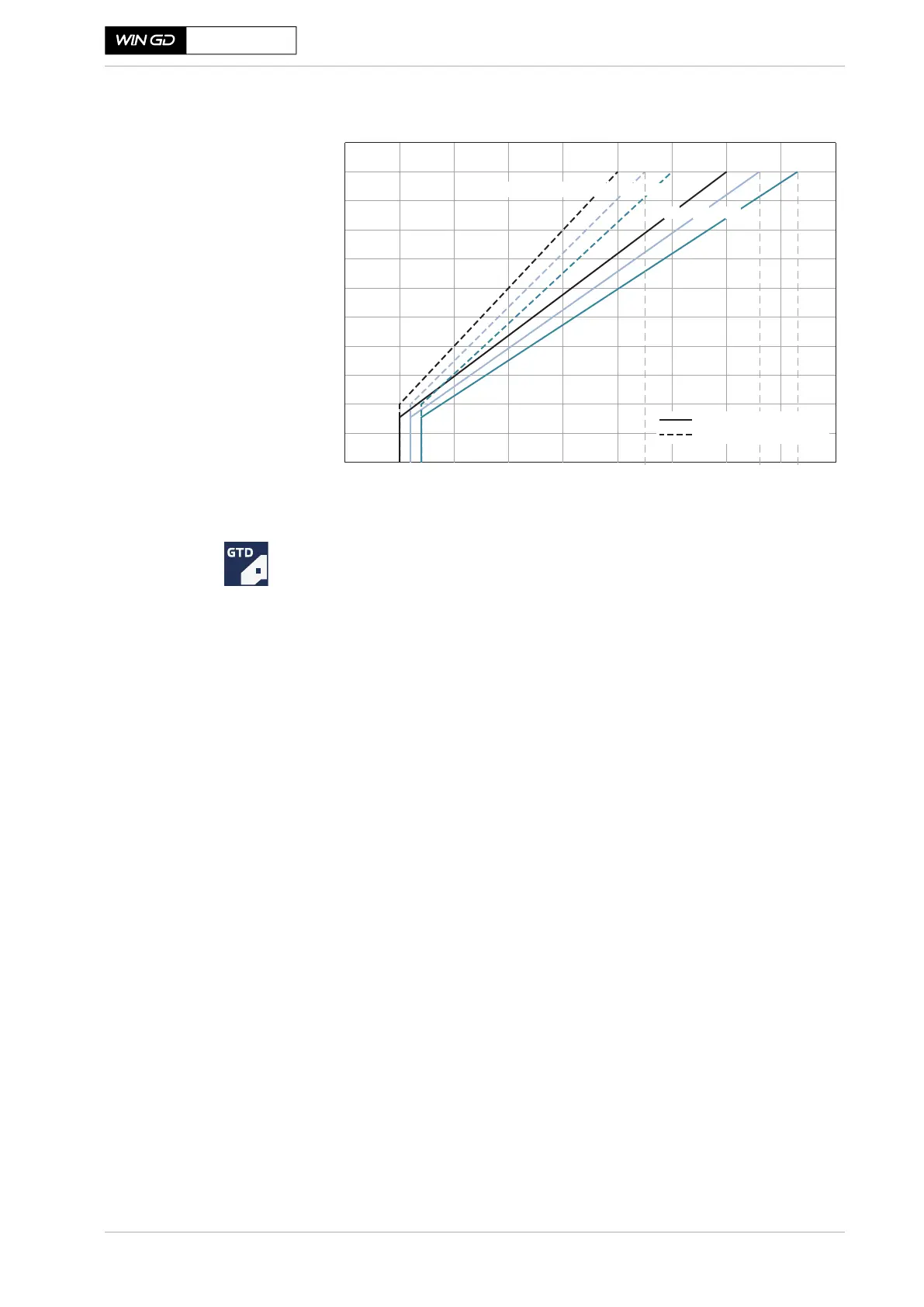
Figure 4-34 Design fuel gas supply pressure requirements
Rating-specific information is available from WinGD’s engine layout applica-
tion GTD.
Case 1 — Example of fuel
gas supply pressure
selection for an
LNG-fuelled vessel
Assumptions:
• An engine with R4 rating is selected.
• No significant amount of NBOG is considered, e.g. just up to 10 %. Typi-
cally, the LNG in the tank has an LHV of approximately 36 MJ/Nm
3
or
higher. Therefore, a fuel gas with an LHV of approximately 36 MJ/Nm
3
is
available under normal conditions. In the unlikely case of a significantly
lower LHV, sufficient engine power output for normal service operation is
available (e.g. more than 90% CMCR power if the LHV is just as low as
32 MJ/Nm
3
).
• A pressure drop of 0.5 bar across the FGSS is considered. The real pressure
drop needs to be calculated by the shipyard or the FGSS supplier (see sec-
tion 4.5.5, 4-51).
Results:
In this case, the ship owner and shipyard have two options to define the fuel gas
supply pressure.
• Option 1:
º The ship owner and the shipyard consider the worst case as design crite-
rion (i.e. an LHV of 32 MJ/Nm
3
to select the fuel gas pressure).
º Based on the R4 rating and the LHV of 32 MJ/Nm
3
, the fuel gas supply
pressure (at the iGPR or the GVU inlet) is selected at 10.5bar(g) fol-
lowing the GTD data.
º Considering the 0.5 bar pressure drop, the fuel gas supply design pres-
sure from the FGSS is defined at 11.0 bar(g).
SM-0739
5
0
10
20
30
40
50
60
70
80
90
100
678910
10.5
6.2
6.4
11 12
12.6
13
13.3
14
Minimum gas pressure [bar(g)]
36 32
28
36 32
28
LHV [MJ/Nm
3
]
Rating on R1 ... R3 line
Rating on R2 ... R4 line
 Loading...