Home
WinGD
Marine Equipment
X62DF-S2.0
WinGD X62DF-S2.0 User Manual
4
of 1
of 1 rating
259 pages
Give review
Manual
Specs
To Next Page
To Next Page
To Previous Page
To Previous Page
Loading...
Marine Inst
allation Manual
2022-03
4-3
4 Ancillary Systems
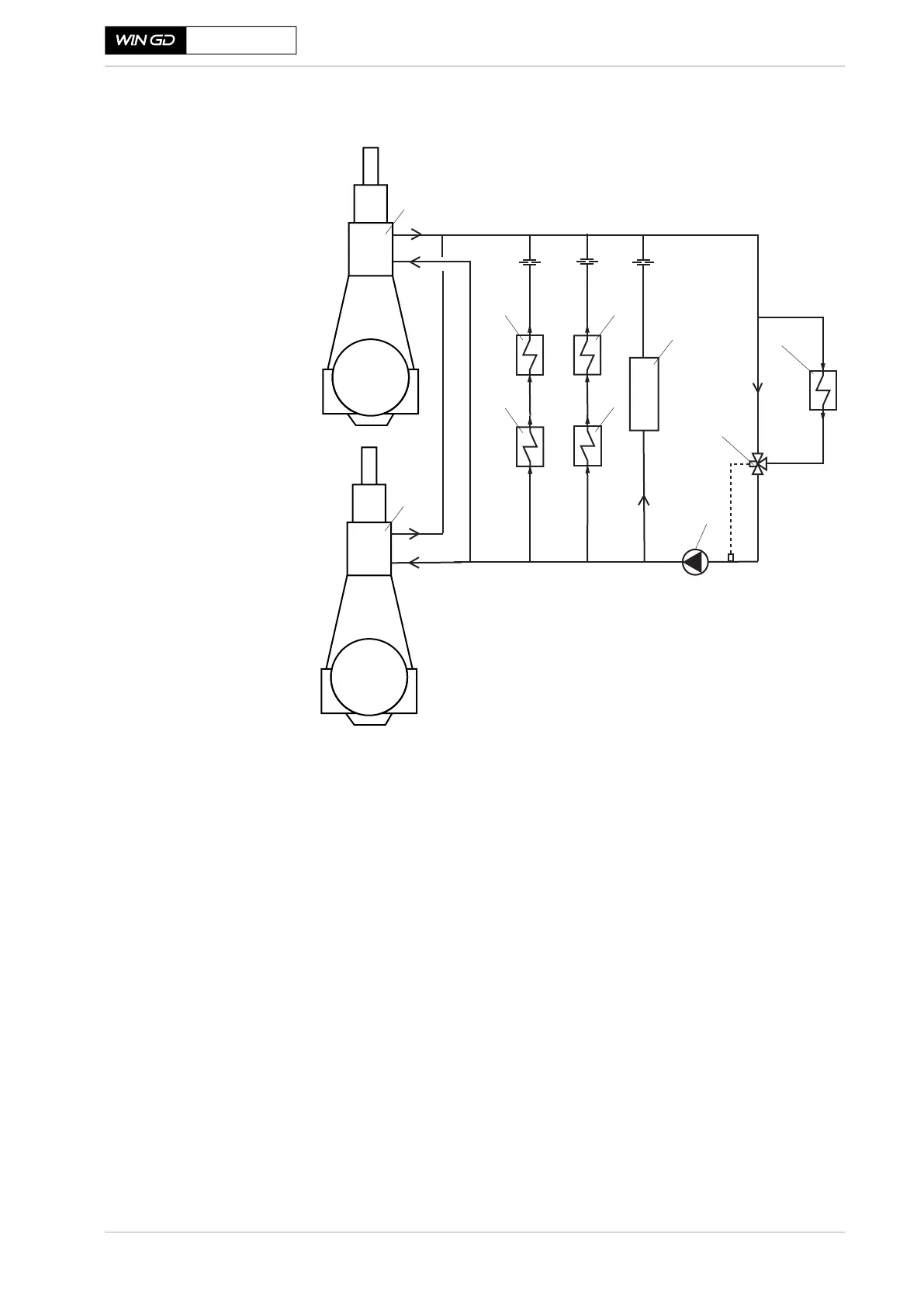
4.1 T
win-engine installation
X62DF-S2.0
Fi
gu
re
4
-
1
L
T
co
ol
in
g
wa
te
r
sy
st
em
f
or
t
wi
n-
en
gin
e
i
nst
a
ll
ati
on
SM-0191
1 Scavenge air cooler (SAC)
2 HT cooling water cooler (engine 1)
3 Lubricating oil cooler (engine 1)
4 HT cooling water cooler (engine 2)
5 Lubricating oil cooler (engine 2)
6
Ancillary plants
7 Central seawater cooler
8 T
emperature control valve
9 Pumps
Main
Engine 2
8 (set-point: 25 °C)
Main
Engine 1
SAC
SAC
9
7
1
2
3
5
6
4
1
81
83
Table of Contents
List of Changes
3
Table of Contents
4
Preface
18
Marine Installation Manual Introduction
18
Explanation of Symbols in this Marine Installation Manual
19
Marine Installation Drawing Set
20
General Technical Data (GTD)
21
Operation and Maintenance Manuals
21
GTD Screenshot
21
Engine Summary
22
Engine Capability and Features
22
Special Characteristics of Short-Stroke Dual-Fuel Engines
22
X62DF-S2.0 Summary Values for Maximum Continuous Rating
22
Special Engine Features
24
Principal Engine Features and Technologies
24
The Icer Technology
25
Primary Engine Data
26
Power/Speed Range of the Wingd X-DF Engines
26
Engine Rating Field - Rating Points
27
Rating Points
27
Engine
27
Principal Engine Dimensions and Weights
28
Principal Engine Dimension Values
28
Principal Engine Dimensions
28
Fuel Operating Modes
29
Operating Modes of the X-DF2.0 Engine with Icer Gas Mode
29
Fuel Split (Energy-Based) for Different Operating Modes
30
Operating Modes of the X-DF2.0 Engine with Icer Gas and Diesel
30
Operation in Gas Mode
31
Gas Mode Operation
31
Shaft Power Meter Requirements
32
The Icer System
32
Shaft Power Meter Parameters
32
The Icer System with One Turbocharger
33
The Icer System with Two Turbochargers
33
Operation in Diesel Mode
34
The Flex System
34
The Flex System Parts
34
Icer Diesel Tier III Mode
35
Operation in a Mixed Fuel Mode
35
Combustion Stability Mode
35
Diesel Fuel Ratio During Active CSM
35
Fuel Sharing Mode
36
Fuel Sharing Mode - Available Operating Window
36
Fuel Sharing Mode - Energy Amount of Different Ratios of Fuel
37
Changeover between Operating Modes
38
Transfers and Gas Trips
38
Engine Power and Speed
40
Introduction to Power and Speed
40
Engine Rating Field
40
Rating Field for the X62DF-S2.0
40
Rating Points
41
Influence of Propeller Diameter and Revolutions
41
Power Range
42
Propeller Curves and Operational Points
42
Sea Trial Power
43
Sea Margin
43
Propeller Curves and Operational Points
43
Light Running Margin
44
Continuous Service Rating
44
Engine Margin
44
Contracted Maximum Continuous Rating
44
Power Range Limits
45
Line 5 Coefficients
47
Line 6 Coefficients
48
Power Range Limits with a Power Take-Off Installation for a FPP
49
PTO Incorporation of Method 1
49
Power Range Diagram of an Engine with a PTO
49
Line 10 Coefficients
50
Power Range Limits for PTO Operation - Method 1
50
PTO Incorporation of Method 2
51
Power Range Limits
51
Prohibited Operation Area
52
The Prohibited Operation Area (CMCR Speed = R1-R2)
52
Prohibited Operation Area for Different Speed Rated Engines
54
Calculating the Prohibited Operation Area for the CMCR Speed
54
CPP Requirements for the Propulsion Control System
57
Engine Installation
58
Engine Dimensions and Masses
58
Engine Dimensions
58
Dismantling Heights for Piston and Cylinder Liner
59
Crane Requirements
59
Thermal Expansion between the Turbocharger and Exhaust Gas
60
Piping
60
Thermal Expansion, DIM. X, Y, Z
60
Content of Fluids in the Engine
61
Conditions and Requirements
62
Pressure and Temperature Ranges
62
Operating Conditions
62
Reference Conditions
62
Design Conditions
62
Ancillary System Design Parameters
63
Electrical Power Requirement
64
Engine Outline Views
65
Platform Arrangement
66
Drawings
66
Minimum Requirements for Escape Routes
66
Minimum Requirements for Headroom
66
Engine Foundation and Seating
67
Engine Load and Force Transmission
67
Engine Foundation Layouts
67
Force Transmission to the Engine Foundation
67
A Comparison of the Standard and Narrow Engine Foundation Layout
67
Engine Installation and Fixation
68
Advantages and Disadvantages for the Standard and Narrow Engine
68
Foundation Bolting
69
Welded Type
69
Side Stopper Installation Arrangement
70
Proposed Designs for Water-Tight Bolting
70
Assembly
71
Assembly of Subassemblies
71
Installation of a Complete Engine
72
Installation of an Engine from Assembled Subassemblies
72
Installation of an Engine in Ship on Slipway
72
Engine and Shaft Alignment
73
Instructions and Limits
73
Tools
73
Engine Coupling
74
Design
74
Machining and Fitting of Coupling Bolts
74
Tightening
74
Installation Drawing
74
Engine Stays
75
Propulsion Shaft Earthing
76
Preventive Action
76
Earthing Device
76
Typical Shaft Earthing Arrangement
77
Typical Shaft Earthing with Condition Monitoring Facility
78
Fire Protection
79
Recommended Quantities of Fire Extinguishing Medium
79
Ancillary Systems
80
Twin-Engine Installation
81
Common and Independent Systems in Twin-Engine Installations
81
Fuel Oil System
81
System
81
Cooling Water System for Twin-Engine Installation
82
The Icer
83
Overview of the Components for the Icer System with One
83
Overview of the Components for the Icer System with Two
84
The Icer Description
85
The Icer System with One Turbocharger
85
The Icer System with Two Turbochargers
85
Turbocharger
86
Turbochargers
86
The Icer Exhaust Gas System
86
Heat Recovery (Economiser)
87
Arrangement of the Additional Economiser (Source: Alfa Laval)
87
Cooling Water System
88
Separate HT Cooling Water Circuit
88
Low-Temperature Circuit
89
Arrangement 1
89
Arrangement 2
89
Arrangement 3
90
LT Cooling Water Circuit - Single Set-Point Temperature
90
LT Cooling Water Circuit - Dual Set-Point Temperatures
90
Low-Temperature Circuit Components
92
High-Temperature Circuit
93
High-Temperature Circuit Components
94
HT Cooling Water Circuit
94
Pre-Heating
97
Pre-Heating from Cooling Water Systems
97
Pre-Heating by Direct Water Circulation
97
Freshwater Generator
98
Cooling Water Treatment
99
Recommended Specifications for Raw Water
99
General Recommendations for the Cooling Water System Design
100
The EGC Circulation Water System
101
Lubricating Oil Systems
102
Lubricating Oil Requirements
102
Main Lubricating Oil System
102
Lubricating Oil System
102
Main Lubricating Oil System Components
103
System Oil
105
Flushing the Lubricating Oil System
105
Lubrication for Turbochargers
105
Cylinder Lubricating Oil System
105
Changeover between Cylinder Lubricating Oils
106
Service Tank and Storage Tank
109
Electrical Trace Heating for System Side Cylinder Lubricating Oil
109
Heating Cable Specification
110
Maintenance and Treatment of Lubricating Oil
111
Drain Tank
112
Fuel Gas System
117
Safety Considerations
117
Operating Principles
118
The Lean-Burn Concept
118
Gas Specifications
120
Methane Number Dependent Engine Output
121
Methane Number Calculation
121
Fuel Gas Supply System
122
Master Gas Fuel Engine Valve
122
Tank Type
122
Section View of an Integrated Membrane Tank
122
Section View of a Free-Standing Type a Tank
123
Section View of a Free-Standing Type B Tank of Moss Design
123
Supplying Fuel Gas
125
Pressurised Type C Tank Solution with NBOG Handling by the
126
Pressurised Type C Tank Solution with NBOG Handling by the
127
Non-Pressurised Tank Solution, Drawn for an LNGC
127
Re-Liquefaction Process
128
Fuel Gas Supply Pressure
130
Design Fuel Gas Supply Pressure Requirements
131
Fuel Gas Supply Pressure Control at the Engine Inlet
133
Fuel Gas Supply Pressure Control at the GVU Inlet
134
Fuel Gas Pressure Level Definitions
134
On-Engine Integrated Gas Pressure Regulation Unit
135
Fuel Gas Supply System with the Igpr
135
Off-Engine Gas Valve Unit
137
Fuel Gas Venting
139
Ventilation of Double-Wall Fuel Gas Piping
139
Purging by Inert Gas
140
Purity of Inert Gas (Engines with Igpr)
141
Purity of Inert Gas (Engines with GVU)
141
Fuel Gas Leak Test
143
Gas Leak Test Sequence (Engines with Igpr)
143
Gas Leak Test Sequence (Engines with GVU)
143
System
143
Pilot Fuel Oil System
144
Specification of the Pilot Fuel Oil Filter on the System Side
146
Fuel Oil System
147
Fuel Oil System Components
147
Feed Pump - Low-Pressure Fuel Oil
148
Pressure Regulating Valve
149
Mixing Unit
149
Mixing Unit
150
Booster Pump - High-Pressure Fuel Oil
151
End-Heater
151
Viscometer
152
MDO/MGO Heat Exchanger
152
Fuel Oil Filters - Arrangement 'A
153
Fuel Oil Filter Arrangement 'A
154
Specification of Automatic Self-Cleaning Filter in Feed System
155
Specification of Automatic Self-Cleaning Filter in Booster System
156
Specification of Duplex Filter in Booster System
157
Fuel Oil Filter - Arrangement 'B
158
Fuel Oil Filter Arrangement 'B
158
Fuel Oil System with Only MDO/MGO or MGO
159
Fuel Oil Feed Pump
160
Fuel Oil Heat Exchanger
160
Fuel Oil Filter
160
Flushing the Fuel Oil System
160
Fuel Oil Treatment
161
Settling Tanks
161
Service Tanks
161
Centrifugal Fuel Oil Separators
161
Pressurised Fuel Oil System
163
Fuel Oil Specification
163
Fuel Oil Viscosity-Temperature Dependency
164
Fuel Oil Viscosity-Temperature Diagram
164
Air Supply System
165
Capacities of Air Compressor and Receiver
166
System Specification
166
Starting Air Compressors
166
Starting Air Receivers
166
Control Air
167
Service and Working Air
167
Leakage Collection System and Washing Devices
168
Sludge Oil Trap Solutions
168
General Description of the Sludge Oil Trap
168
Solution 1: a Constantly-Drained Sludge Oil Trap with Separate Sludge Accumulation
168
Solution 2: a Manually Bottom-Drained Sludge Oil Trap
170
Design Proposal of Wingd's Sludge Oil Trap
170
Design Proposal of a Manually Bottom-Drained Sludge Oil Trap
171
Solution 3: an Automatically Bottom-Drained Sludge Oil Trap
172
Design Proposal of an Automatically Bottom-Drained Sludge Oil Trap
173
Draining of Exhaust Uptakes
174
Air Vents
174
The Icer Drainage System
175
Arrangement of the Icer Drainage System for Installations Which Exclusively Run in Gas Mode
175
Arrangement of the Icer Drainage System for Installations Which Include Icer Diesel Tier III Mode Operation
176
The Icer Drainage System for Installations with Only Gas Mode
176
The Icer Drainage System for Installations with Gas and Diesel
177
The Icer Drainage System with Two Separate Water Treatment Units
178
Exhaust Gas System
180
The Icer Exhaust Gas System
181
Example of an Exhaust Gas Piping Arrangement with One
183
Example of an Exhaust Gas Piping Arrangement with Two
183
Engine Room Ventilation
184
Ventilation Requirements
184
Ventilation Arrangement
185
Arrangement 1 - Engine Room Ventilation System
185
Arrangement 2 - Direct Engine Ventilation System
185
Ventilation System Arrangement 1 - Engine Room Ventilation
186
Ventilation System Arrangement 2 - Direct Engine Ventilation
187
Air Intake Quality
188
Outside Ambient Air Temperature
190
Piping
191
Pipe Connections
191
Fluid Velocities and Flow Rates
191
PTO, PTI, PTH and Primary Generator Applications
192
Requirements
192
Arrangements for PTO, PTI, PTH and Primary Generator
192
Arrangements for PTO, PTI, PTH
193
Application Constraints
194
Service Conditions
196
Speed
196
Engine Automation
199
Denis
199
Engine Automation Architecture
199
DENIS Concept
200
Interface Definition
200
Approved Propulsion Control Systems
200
Engine Management and Automation Concept
200
DENIS Specification
201
DENIS Interface Specification
201
DENIS Propulsion Control Specification
201
Propulsion Control Systems
202
Suppliers of Remote Control Systems
202
Remote Control System
202
Functions of the Propulsion Control System
204
Remote Control System
204
Safety System
204
Telegraph System
204
Local Manual Control
204
ECR Manual Control Panel
204
Options
205
Propulsion Control
205
Recommended Manoeuvring Characteristics
206
Recommended Manoeuvring Steps and Warm-Up Times for FPP
207
Full Sea Load Steps in FPP Load-Up Program
207
Recommended Manoeuvring Steps and Warm-Up Times for CPP
208
Full Sea Load Steps in CPP Load-Up Program
208
Alarm and Monitoring System
209
Integrated Solution
209
Split Solution
209
Alarm Sensors and Safety Functions
210
Signal Processing
210
Requirements of Wingd and Classification Societies
210
Additional Class Requirements for Alarm Sensors and Safety
210
Wingd Integrated Digital Expert (Wide)
211
Data Collection
211
The Wide Data Collection and Analysis Process
211
Engine Diagnostic Module
212
The Wide Installation Process
213
Engine Dynamics
214
External Mass Forces and Moments
215
Balancing of Mass Forces and Moments
215
Countermeasures for Second Order Vertical Mass Moments
216
Integrated Electrical Balancer (Ielba)
216
Major Components and Details of the Ielba
216
Electrically-Driven Compensator (External Compensator)
217
Locating an Electrically-Driven Compensator
217
Power Related Unbalance
218
External Lateral Forces and Moments
219
Forces through the Engine
219
Lateral Vibration Types
220
H-Type Vibration
220
X-Type Vibration
220
Lateral Vibration - X-Type and H-Type
220
Reduction of Lateral Vibration
221
Lateral Stays
221
Lateral Stays Shifting the Resonance Frequency above Nominal
221
General Arrangement of Hydraulic Type Stays for One-Side
222
General Arrangement of Hydraulic Type Stays for Both-Side
222
Determining the Minimum Number of Required Lateral Stays
223
Twin-Engine Installations with Two Standard Engines
224
Engine Stays Arrangement on the Exhaust Side
225
Engine Stays Arrangement on the Engine's Fuel Side
225
Electrically-Driven Compensator
226
Engine Stays Arrangement on both Engine Sides
226
Longitudinal Vibration (Pitching)
227
Reduction of Longitudinal Vibration (5-Cylinder Engines)
227
Torsional Vibration
229
Reduction of Torsional Vibration
229
Low-Energy Vibrations
230
High-Energy Vibrations
230
PTO/PTI Systems Effect on Torsional Vibration
231
Axial Vibration
232
Reduction of Axial Vibration
232
Whirling Vibration
233
Hull Vibration
234
Countermeasures for Dynamic Effects
235
External Mass Moments and Vibrations
235
Countermeasures for External Mass Moments
235
Countermeasures for Lateral and Longitudinal Vibrations
235
Countermeasures for Torsional and Axial Vibrations of the Shafting
235
Synchro-Phasing System in Twin Engines
236
Concept
236
Resulting Vibration from SPS Combinations
236
Components and Control
237
Synchro-Phasing System
237
Operating Modes and Restrictions
238
Order Forms for Vibration Calculation & Simulation
239
Engine Emissions
240
Exhaust Gas Emissions
240
Emissions Comparison between X-DF2.0, X-DF and Diesel Engines
240
Regulation and Calculation Criteria for Nox Emissions
242
Regulation and Calculation Criteria for Sox Emissions
242
Regulation and Calculation Criteria for CO2 Emissions
242
Operation
243
PM Emissions
244
Icer Diesel Tier III Mode
244
Engine Noise
245
Air-Borne Noise
245
Exhaust Noise
247
Exhaust Noise Reference Point
247
Sound Pressure Level at Funnel Top of Exhaust Gas System
248
Structure-Borne Noise
249
Structure-Borne Noise Level at Engine Feet Vertical
249
Engine Dispatch
250
Engines to be Transported as Part Assemblies
250
Protection of Disassembled Engines
250
Removal of Rust Preventing Oils after Transport
250
Internal Parts
250
External Parts
250
Appendix
251
Classification Societies
251
List of Classification Societies
251
List of Acronyms
252
Dimensions for Internal Combustion Engines
255
Dimensions
255
Approximate Conversion Factors
257
Conversion Factors
257
4
Based on 1 rating
Ask a question
Give review
Questions and Answers:
Need help?
Do you have a question about the WinGD X62DF-S2.0 and is the answer not in the manual?
Ask a question
WinGD X62DF-S2.0 Specifications
General
Brand
WinGD
Model
X62DF-S2.0
Category
Marine Equipment
Language
English
 Loading...