Marine Installation Manual 2022-03 6-3
6 Engine Dynamics
6.1 External mass forces and moments
X62DF-S2.0
Second and
fourth order moments
Second (M
2V
) and fourth (M
4V
) order vertical mass moments are also generated,
although these magnitudes will vary depending on engine type and number of
cylinders. Unless a problematic vessel design leads to unfavourable vibration,
there is normally no cause for concern for engines with 7 cylinders or more.
However, 5- and 6-cylinder engines are known to generate high magnitudes of
unbalanced second order vertical mass moments (M
2V
) and should therefore be
carefully considered. Consequently, for 5- and 6-cylinder engines WinGD
strongly recommends that the impact of the second order vertical mass moment
on the vessel is carefully checked. In cases where the investigation reveals a pos-
sible problem, WinGD recommends to consider the installation of one of the fol-
lowing countermeasures, designed to reduce the effects of second order vertical
mass moments to acceptable values.
6.1.2 Countermeasures for second order vertical mass moments
WinGD strongly recommends the use of either of the following countermeasures
for 5- and 6-cylinder engines:
• Engine-fitted electric balancer(s) (iELBA)
• An electrically-driven compensator, fitted to the ship’s structure
These countermeasures should also be considered for other cylinder number en-
gines if the second order vertical mass moments (M
2V
) surpass the necessary
limits. However, suitability will vary for different engines and vessel design, as
well as the status of the project, i.e. still in design phase, or retrofitting.
Integrated electrical balancer (iELBA)
The iELBA is structurally integrated into the engine and is installed on the free
end and/or the driving end. For engines with the turbocharger located at the
driving end side, only a single iELBA can be installed on the free end. The
iELBA is comprised of two shafts with counterweights, connected with gear
wheels and driven by one electric motor. A frequency converter controls the
speed of the electric motor. This frequency converter and the control system are
installed in an electrical cabinet in the control room. Alternatively, these items
can be installed in the engine room.
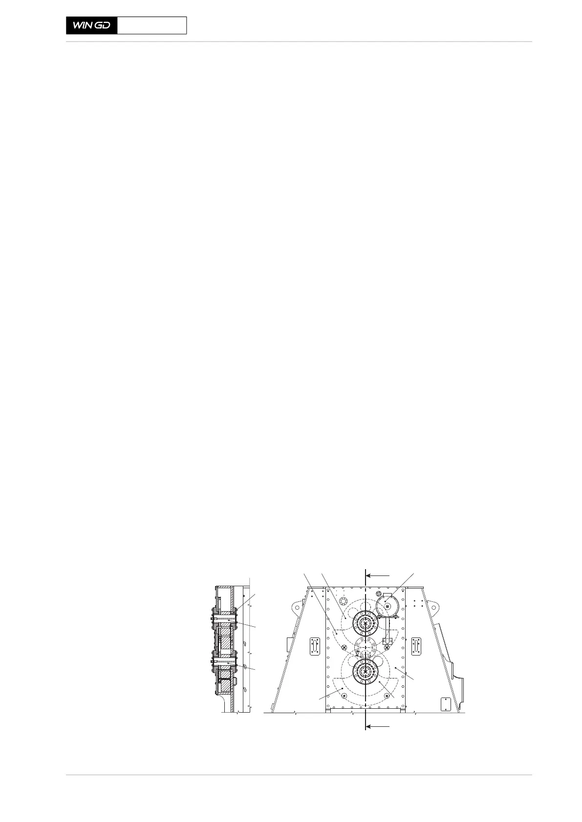
Figure 6-2 Major components and details of the iELBA
SM-0272
A
1 Gear wheel
2 Counterweight
3 Electic motor
4 Shaft
5 Bearing
6 Housing
1
2
2 1
4
4
A-A
3
6
A
5
 Loading...