Marine Installation Manual 2022-03 4-68
4 Ancillary Systems
4.7 Fuel oil system
X62DF-S2.0
4.7 Fuel oil system
The latest version of the Marine Installation Drawing Set relevant for the fuel
oil system (DG 9723) is provided on the WinGD webpage under the following
link:
MIDS
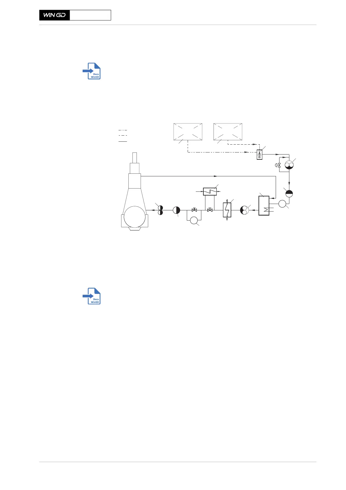
Figure 4-45 shows the installation principle for maximum fuel flexibility.
Figure 4-45 Fuel oil system
Further information about MDO/MGO fuels is available in the separate Con-
cept Guidance (DG 9723). This considers additional design options for the fuel
oil system, as well as optional heat exchangers for better viscosity regulation
when changing between HFO/LSHFO and MDO/MGO.
This is provided on the WinGD webpage under the following link:
Concept Guidance Distillate Fuels
Fuel consumption
Data of fuel consumption should be taken from the project-specific GTD data
sheet.
4.7.1 Fuel oil system components
The following components are associated with a fuel oil system of maximum fuel
flexibility, i.e. operation on heavy fuel oils and distillates, as indicated in Figure
4-45. Therefore, the following section considers a fuel oil viscosity of 700 cSt at
50 °C.
In cases where only distillate fuels are considered, the system can be simplified
(as explained in section 4.7.2, 4-80), however consideration must be given the
reduction in fuel oil viscosity.
Main
Engine
1 HFO/LSHFO settling, storage and separation system
2 MDO/MGO settling, storage and separation system
3 Automatic fuel changeover unit
4 Feed pump - Low pressure
5 Automatic self-cleaning filter
6 Flow meter
FM
Pm
HFO/LSHFO piping
MDO/MGO piping
Common piping
4
7
5
8
10
6
3
1
2
12
Pm
PLFURQV
9
LT Cooling
water system
7 Fuel oil mixing unit
8 Booster pump - High pressure
9 Fuel oil end-heater
10 MDO/MGO heat exchanger
11 Viscometer
12 Duplex filter
HFO/LSHFO
MDO/MGO
PRV
5
V
11
 Loading...