Marine Installation Manual 2022-03 4-98
4 Ancillary Systems
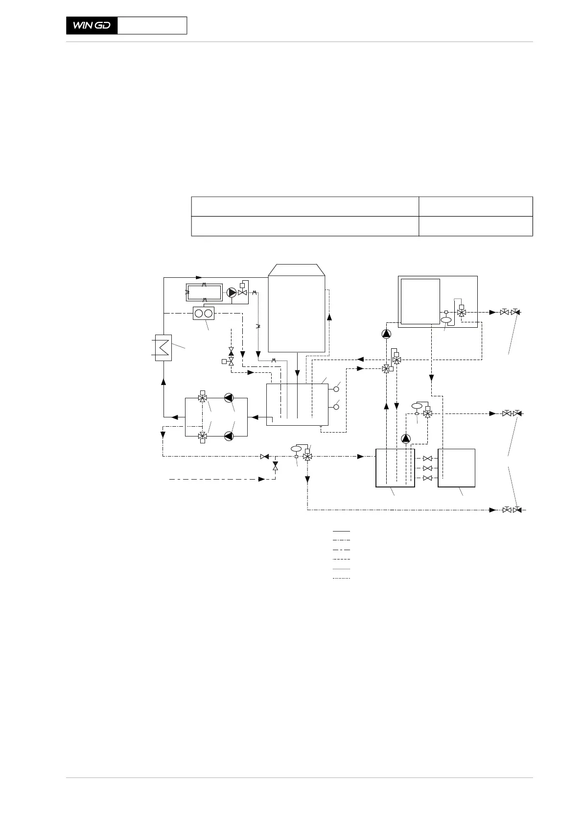
4.9 Leakage collection system and washing devices
X62DF-S2.0
If the oil-in-water content in the EGC drain tank exceeds 15 ppm, oil removal by
means of a water treatment unit is then required. Otherwise, if the oil-in-water
content of the water in the EGC drain tank does not exceed 15 ppm and the
vessel is operating outside an area of restricted overboard discharge, the water
can then be directly pumped overboard. Figure 4-58 provides a sketch of the
iCER drainage system for installations with gas and diesel Tier III mode opera-
tion.
Chemical consumption
during diesel Tier III
mode operation
Table 4-15 Chemicals required for treatment of the EGC circulation water
Figure 4-58 The iCER drainage system for installations with gas and diesel Tier III
mode operation
Alternatively, an iCER drainage system with two separate water treatment units
can be considered. One unit handles the bleed-off water and the SAC drain water
(during iCER operation), the other handles the EGC circulation water as shown
in Figure 4-59, 4-99.
Coagulant consumption (if applicable): According to supplier
Caustic soda (50% m/m NaOH) consumption: 0.2 l/MWh
SM-0695
o/w
o/w
EGC
Separator
Coagulant
Dosing
pump
NaOH
pH QC
LT
LSH
1
2
3
Overboard
6a
1 EGC circulation water cooler
2 EGC circulation water pumps
(frequency controlled)
3 EGC circulation water tank
4 EGC drain tank
5 EGC sludge tank
6 Oil-in-water monitoring sensor:
6a UV type
6b Standard type
7 Bleed-off valves
8 Water analyser (pH and quality)
9 Level transmitter
10 High-level switch
EGC circulation water system
Bleed-off system
Water sampling line
Water treatment system
pH-neutralisation dosing unit
Venting pipes
with manual
override
7
o/w
6a
6b
4
5
Fresh water
refill
8
Overboard
from SAC drain during
iCER operation
9
10
o/w
Water
treatment
unit
6b
 Loading...