Marine Installation Manual 2022-03 4-102
4 Ancillary Systems
4.10 Exhaust gas system
X62DF-S2.0
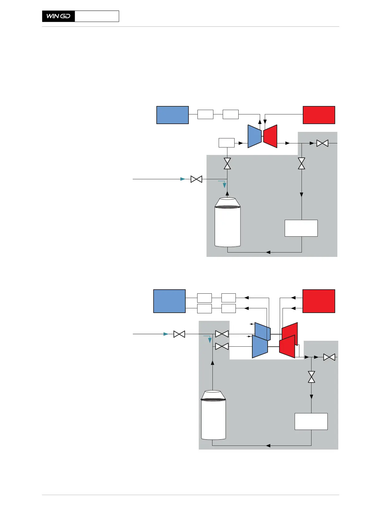
The iCER exhaust gas system
The iCER is designed to recirculate approximately 50 % of the exhaust gas
during gas mode operation and a reduced amount during diesel Tier III mode op-
eration. The recirculation is through a low-pressure path, allowing for the full
use of the turbocharger’s capacity.
Figure 4-61 The iCER exhaust gas system
Figure 4-62 The iCER exhaust gas system (example shown with two turbochargers)
SM-0669
EGC
Purge line (in)
Economiser
EGC: Exhaust Gas Cooler
(with demister at outlet)
FRV: Flow Regulating Valve
SOV: Shut-O Valve
BPV: Back Pressure Valve
SAC: Scavenge Air Cooler
WMC: Water Mist Catcher
FRV
BPV
SOV
Exhaust gas
receiver
SAC
WMC
Scavenge
air receiver
WMC
Colour code
White area: Components installed on the engine
Grey area: Components installed in
the engine room
Purge line (in)
Economiser
EGC: Exhaust Gas Cooler
(with demister at outlet)
FRV: Flow Regulating Valve
SOV: Shut-O Valve
BPV: Back Pressure Valve
SAC: Scavenge Air Cooler
WMC: Water Mist Catcher
EGC
SOV
BPV
FRV
SAC
WMC
SAC
WMC
Colour code
White area: Components installed on the engine
Grey area: Components installed in
the engine room
 Loading...