Marine Installation Manual 2022-03 3-3
3 Engine Installation
3.1 Engine dimensions and masses
X62DF-S2.0
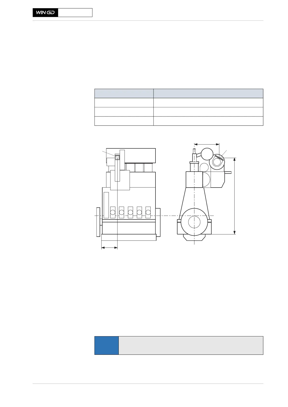
3.1.3 Thermal expansion between the turbocharger and exhaust gas
piping
Before making expansion pieces, enabling connections between the engine and
external engine services, the thermal expansion of the engine and turbocharger
has to be taken into account. The engine expansion is defined (from ambient
temperature 20 °C to service temperature 55°C) as follows (see also Figure 3-2):
Figure 3-2 Thermal expansion, dim. X, Y, Z
Calculating thermal
expansion
Δx (Δy, Δz) = X (Y, Z) • α • ΔT
where:
Δx, Δy, Δz .. = thermal expansion
X, Y, Z ...... = distance as per relevant pipe connection plan and outline drawing
α .............. = 1.15 • 10
-5
(coefficient of thermal expansion)
ΔT ............ = difference between service temp. and ambient temp. [°C]
Expansion Distance from ...
Transverse expansion (X) ... crankshaft centreline to centre of gas outlet flange
Vertical expansion (Y) ... bottom edge of bedplate to centre of gas outlet flange
Longitudinal expansion (Z) ... engine bedplate aft edge to centre of gas outlet flange
a) Gas outlet flangeDimensions X, Y, Z
SM-0054
NOTE
For thermal expansion values of the turbocharger, please see the spec-
ifications of the turbocharger maker.
 Loading...