218 www.xilinx.com 7 Series FPGAs GTP Transceivers User Guide
UG482 (v1.9) December 19, 2016
Chapter 5: Board Design Guidelines
Notes relative to Figure 5-1:
1. Nominal values. Refer to DS181
, Artix-7 FPGAs Data Sheet: DC and Switching
Characteristics for values and tolerances.
MGTAVCC In (Pad) MGTAVCC is the analog supply for the internal analog circuits of the GTP
Quad tile. This includes the analog circuits for the PLLs, transmitters and
receivers. Most packages have multiple groups of power supply connections
in the package for MGTAVCC. Refer to the package pin definitions to identify
in which power supply group a specific GTP Quad is assigned. Nominal
voltage = 1.0 VDC.
MGTAVTT In (Pad) MGTAVTT is the analog supply for the transmitter and receiver termination
circuits of the GTP Quad tile. Most packages have multiple groups of power
supply connections in the package for MGTAVTT. Refer to the package pin
definitions to identify which power supply group a specific GTP Quad is
assigned. Nominal voltage = 1.2 VDC.
Table 5-1: GTP Quad Pin Descriptions (Cont’d)
Pins Direction Description
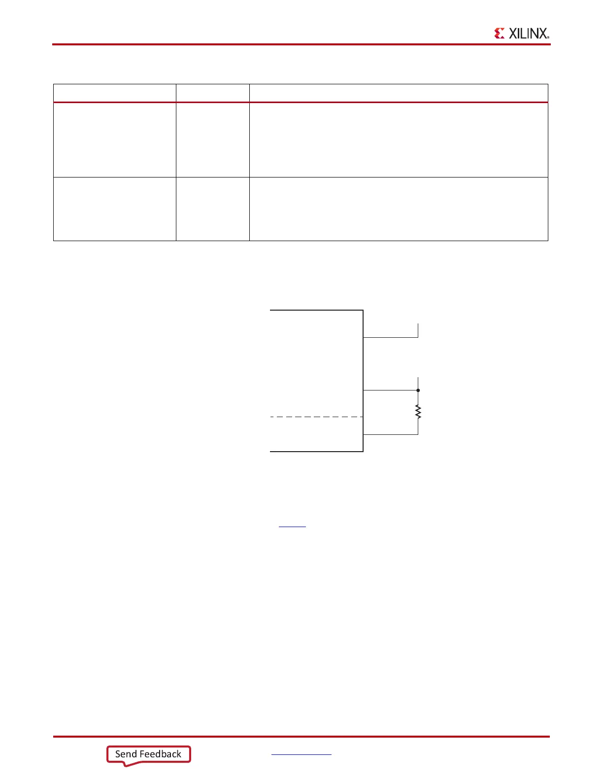
X-Ref Target - Figure 5-1
Figure 5-1: Artix-7 FPGA GTP Power Supply Connections
MGTAVTT
100 ohm
1%
GTP Quad
MGTAVCC
1.0V
(1)
MGTRREF
1.2V
(1)
UG482_c5_01_080612

 Loading...


