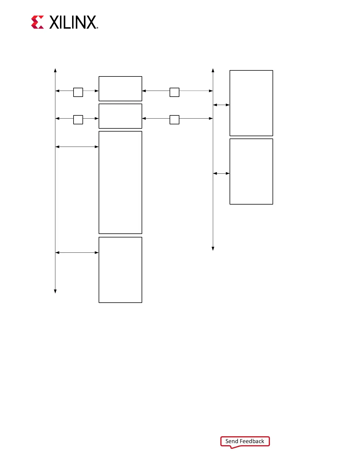
Figure 13: I2C0 and I2C1 Bus Connectivity Overview
U210
L/S
U211
0x74
0
1
2
3
4
5
6
7
U35 TCA9548A
DC_I2C
FMCP1_IIC
FMCP2_IIC
DDR4_DIMM1
LPDDR4_SI570_CLK2
LPDDR4_SI570_CLK1
HSDP_SI570
8A34001
L/S
0x75
0
1
2
3
4
5
6
7
U214 TCA9548A
SFP0_IIC
SFP1_IIC
QSFP1_I2C
NC
NC
NC
NC
NC
0x74
0
1
2
3
4
5
6
7
U35 TCA9548A
0x75
0
1
2
3
4
5
6
7
U214 TCA9548A
MAX6643_OT_B
MAX6643_FANFAIL_B
PMBUS2_INA226_ALERT
MAX6643_FULLSPD
FMCP1_FMC_PRSNT_M2C_B
FMCP2_FMC_PRSNT_M2C_B
FMCP1_FMCP_PRSNT_M2C_B
FMCP2_FMCP_PRSNT_M2C_B
VCCINT_VRHOT_B
8A34001_EXP_RST_B
PMBUS_ALERT
PMBUS1_INA226_ALERT
GPIO
Expander
0x20
P00
P01
P04
P07
P10
P11
P12
P13
P14
P15
P16
P17
U233 TCA6416A
0x74
0
1
2
3
4
5
6
7
U33 TCA9548A
PMBUS
PMBUS1_INA226
PCIE_CLK
PMBUS2_INA226
NC
zSFP_SI570
USER_SI570_1_CLOCK
NC
0
1
2
3
4
5
6
7
I2C0
System Controller
PS Bank 501
U125 XCZU4EG
U212
L/S
U213
L/S
Versal ACAP
PS Bank 501
U1
I2C0 I2C1
I2C1
I2C
MUX
I2C
MUX
#2
I2C
MUX
#1
X23200-100719
PMC MIO[46:47] I2C0 Bus
[Figure 3, callout 11]
Bus I2C0 connects the XCVC1902 U1 PS bank 501 and the XCZU4EG system controller U125
PS bank 501 to a GPIO 16-bit port expander (TCA6416A U233) and I2C switch (TCA9548A
U33). The port expander enables accepng various fan controller, FMCP connector, and power
system status inputs. Bus I2C0 also provides access to power system PMBus power controllers
and INA226 power monitors, as well as three SI570 components via the U33 TCA9548A switch.
TCA6416A U233 is pin-strapped to respond to I2C address 0x20. The TCA9548A U33 switch is
set to 0x74.
Chapter 3: Board Component Descriptions
UG1366 (v1.0) January 7, 2021 www.xilinx.com
VCK190 Board User Guide 36

 Loading...


