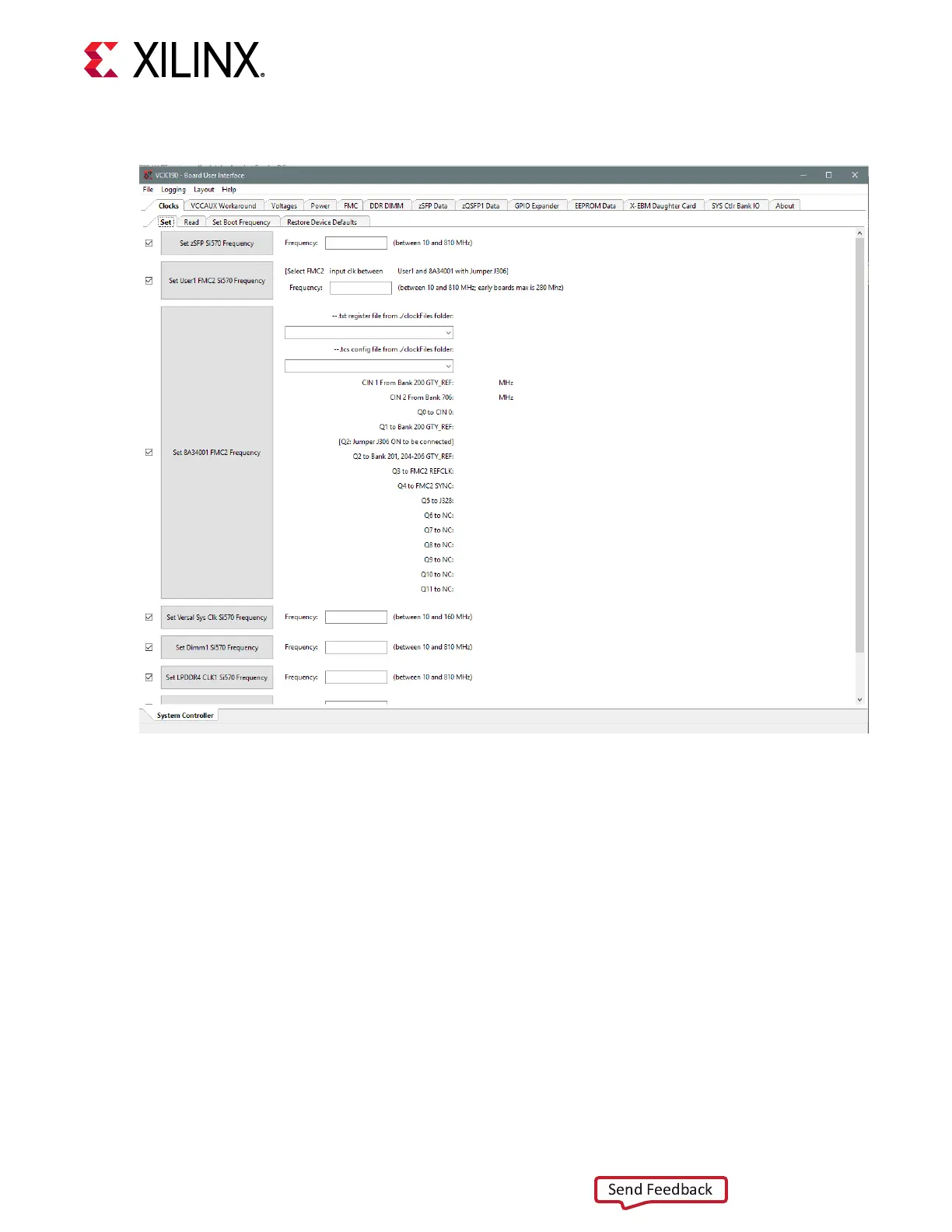
Figure 25: System Controller User Interface
On rst use of the SCUI, select FMC → Set VADJ → Boot-up tab and click USE FMC EEPROM
Voltage. The SCUI buons gray out during command execuon and return to their original
appearance when ready to accept a new command.
See the VCK190 Soware Install and VCK190 Board Setup Tutorial (XTP619) and the System
Controller Tutorial (XTP618) (which includes instrucons for changing VCK190 clocks) for more
informaon on installing and using the system controller UI.
Switches
[Figure 3, callout 6 and 30]
The VCK190 board includes power and conguraon switches:
• SW13 power on/o slide switch
• SW1 U1 ACAP PS bank 503 4-pole mode DIP switch
Chapter 3: Board Component Descriptions
UG1366 (v1.0) January 7, 2021 www.xilinx.com
VCK190 Board User Guide 64

 Loading...


